Fresh & Hardened Concrete: Workability, Strength, Elasticity & Durability
In this chapter (1 topics)
On this page
- 1. Topic Title & Authoritative References
- 2. Prerequisites & Learning Objectives
- Prerequisites
- Learning Objectives
- 3. Rheology & Workability of Fresh Concrete
- 3.1 Factors Influencing Workability
- 3.2 Standard Workability Tests (IS 1199 Part 2)
- 3.3 Workability Classification Matrix (IS 456:2000 Cl. 7.1)
- 3.4 Rheological Defects: Segregation & Bleeding
- 4. Water-Cement Ratio, Hydration Stoichiometry & Gel-Space Ratio
- 4.1 Abram's Water-Cement Ratio Law (Duff Abrams, 1918)
- 4.2 Stoichiometric Water Demand for Complete Hydration
- 4.3 Powers' Gel-Space Ratio Theory (T. C. Powers, 1948)
- 5. Compressive Strength & Failure Mechanics (IS 516)
- 5.1 Standard Compressive Test on Cubes (IS 516)
- 5.2 Platen Restraint & The Cube vs. Cylinder Discrepancy
- 5.3 Concrete Maturity Concept (Nurse-Saul Equation)
- 6. Tensile Strength & Modulus of Rupture (IS 516)
- 6.1 Flexural Tensile Strength (Modulus of Rupture, fcr)
- 6.2 Brazilian Splitting Tensile Strength (fct) (IS 516 Part 1 Sec 2 / ASTM C496)
- 7. Elastic Modulus, Creep, Shrinkage & Durability (IS 456)
- 7.1 Modulus of Elasticity (Ec)
- 7.2 Creep of Concrete & Effective Modulus (Ece)
- 7.3 Drying Shrinkage
- 7.4 IS 456:2000 Durability Mandates (Tables 3, 4, and 5)
- 8. Solved Numerical Problem 1: Compacting Factor & Powers' Gel-Space Ratio
- Problem Statement
- Step-by-Step Analytical Solution
- 9. Solved Numerical Problem 2: Flexural Tensile & Split Tensile Calculations
- Problem Statement
- Step-by-Step Analytical Solution
- 10. Solved Numerical Problem 3: Elastic Modulus, Creep Kinetics & Long-Term Deflection
- Problem Statement
- Step-by-Step Analytical Solution
- 11. Common Misconceptions, Pitfalls & Field Traps
- 12. Multi-Exam Comparative Summary & High-Yield Facts Table
- 13. Comprehensive Glossary of Technical Terms
- 14. References & Standard Codes
1. Topic Title & Authoritative References
Title: Comprehensive Rheology of Fresh Concrete, Standard Workability Testing, Water-Cement Ratio & Gel-Space Ratio Mechanics, Compressive & Tensile Failure Modes, Elasticity, Creep & Shrinkage Phenomena, and IS 456:2000 Durability Mandates.
Primary Standards & Authoritative Specifications:
- IS 456:2000: Plain and Reinforced Concrete — Code of Practice (Fourth Revision).
- IS 516:1959 / 2021: Hardened Concrete — Methods of Test for Strength of Concrete (Parts 1 to 4: Compressive, Flexural, and Split Tensile Strengths).
- IS 1199 (Parts 1 to 7): Fresh Concrete — Methods of Sampling, Testing and Analysis (Part 2: Workability; Part 3: Density and Yield; Part 7: Air Content).
- ASTM C39 / C39M: Standard Test Method for Compressive Strength of Cylindrical Concrete Specimens.
- ASTM C496 / C496M: Standard Test Method for Splitting Tensile Strength of Cylindrical Concrete Specimens.
2. Prerequisites & Learning Objectives
Prerequisites
- Solid mechanics: uniaxial stress, triaxial confinement, shear planes, Mohr-Coulomb failure criteria.
- Material physics: capillary forces, surface energy, elastic and viscoelastic deformation kinetics.
- Chemical fundamentals of hydration: C-S-H gel formation, porosity partitions, and stoichiometric water demand.
Learning Objectives
- Formulate the rheology of fresh concrete, identifying mechanisms of segregation and bleeding, and select appropriate workability testing apparatus (Slump Cone, Compacting Factor, Vee-Bee Consistometer, Flow Table) based on consistency regimes.
- Apply Abram's Water-Cement Ratio Law and Powers' Gel-Space Ratio theory to calculate theoretical compressive strength and porosity partitions.
- Analyze platen friction confinement in standard cubes versus unconfined stress distributions in cylinders, deriving the empirical strength conversion ratio ().
- Evaluate tensile strength test configurations: Modulus of Rupture () under two-point loading and Brazilian Diametral Splitting Tensile Strength ().
- Determine short-term static secant modulus () and long-term effective modulus () accounting for time-dependent creep and shrinkage.
- Enforce IS 456:2000 Table 3, 4, and 5 durability matrices across all environmental exposure classes (Mild to Extreme).
3. Rheology & Workability of Fresh Concrete
Workability is defined as the amount of useful internal work necessary to overcome internal friction between individual aggregate particles and between concrete and the formwork/reinforcement to achieve compaction without segregation.
3.1 Factors Influencing Workability
- Water-Cement Ratio: Primary driver. Increasing water content increases paste fluidity and lubricates aggregate surfaces, but excessive water lowers strength, triggers bleeding, and increases porosity.
- Aggregate Shape & Texture: Smooth, rounded river gravels possess the lowest specific surface area and minimum void ratio (), maximizing workability for a given w/c ratio. Angular crushed stones increase particle friction, requiring more paste.
- Aggregate Size: Larger maximum aggregate size ( vs ) reduces total surface area per unit volume, reducing water demand.
- Grading & Sand Content: Well-graded continuous mixtures minimize interstitial voids. Excess sand increases surface area and paste demand; deficient sand causes harsh, segregating mixes.
- Admixtures: Plasticizers and superplasticizers disperse flocculated cement grains via electrostatic repulsion and steric hindrance, drastically increasing workability without added water.
- Temperature & Time: Workability drops with elapsed time (slump loss) and rising ambient temperatures due to accelerated hydration kinetics and evaporation.
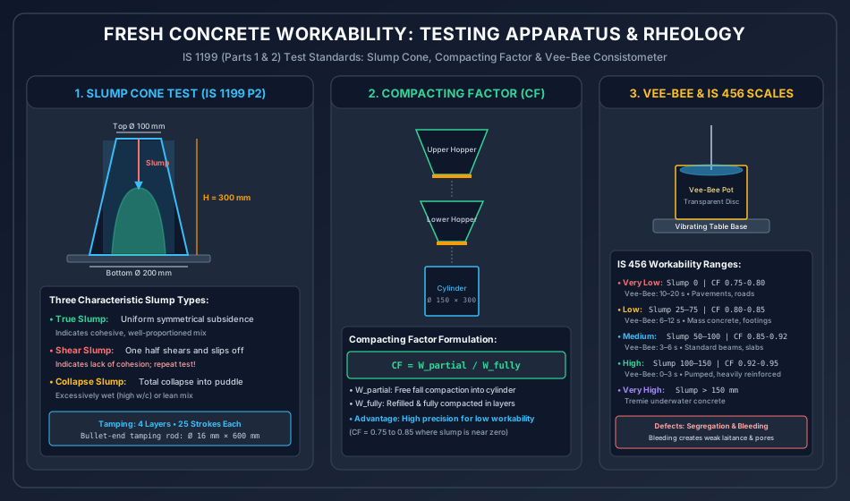
3.2 Standard Workability Tests (IS 1199 Part 2)
1. Slump Cone Test
- Apparatus: Smooth internal metal frustum of a cone:
- Top internal diameter:
- Bottom internal diameter:
- Height:
- Metal thickness:
- Tamping Rod: Bullet-ended steel rod of diameter and length.
- Procedure: Placed on a flat, non-porous base plate. Filled in four equal layers by height ( each). Each layer is tamped with the rounded end of the rod. The top surface is struck off flush, and the cone is lifted vertically upward smoothly within .
- Slump Measurement: The vertical subsidence of the concrete center below the top of the mold is measured to the nearest .
- Three Failure Types:
- True Slump: Symmetrical, uniform subsidence without shear failure. Reflects cohesive, well-proportioned concrete.
- Shear Slump: One half of the cone slips down an inclined shear plane. Indicates lack of cohesion or harshness; test must be repeated.
- Collapse Slump: Complete collapse into an unshaped puddle. Indicates overly wet, lean, or segregated concrete.
2. Compacting Factor Test
- Principle: Measures the degree of compaction achieved by a standardized amount of gravitational work (free fall). Highly sensitive for dry and lean mixtures () where slump is practically zero.
- Apparatus: Two conical hoppers (upper and lower) with quick-release trap doors mounted vertically above a cylindrical receiving mold of diameter and height.
- Procedure:
- Concrete is placed gently into the upper hopper until level.
- The upper trap door is opened; concrete falls freely into the lower hopper.
- The lower trap door is opened; concrete falls freely into the cylindrical mold.
- Excess concrete above the top rim is struck off flush with a trowel.
- The cylinder with partially compacted concrete is weighed: Net mass .
- The cylinder is emptied, refilled with identical concrete in layers, and fully vibrated/rodded until compacted: Net mass .
- Compacting Factor ():
3. Vee-Bee Consistometer Test
- Principle: Measures the relative effort required to reshape a mass of fresh concrete from a conical slump form to a flat cylindrical form using vibration. Preferred for stiff, zero-slump roller-compacted or precast concrete.
- Apparatus: Slump cone placed inside a cylindrical metal pot ( dia, height) mounted on an electric vibrating table ( at amplitude). Fitted with a swiveling transparent plastic disc.
- Procedure: The slump cone is filled and lifted. The transparent horizontal disc is lowered onto the slumped concrete cone. The vibrator and stopwatch are started simultaneously.
- Vee-Bee Time: The time in seconds (Vee-Bee Seconds, ) required for the concrete surface to fully flatten and the bottom surface of the transparent disc to become completely coated with cement grout.
4. Flow Table Test
- Apparatus: Rigid flat wooden table () covered with a smooth metal plate. A central brass frustum mold ( top dia, bottom dia, height) is filled in two equal layers, rodded, and stripped.
- Operation: The table top is raised and dropped through a cam mechanism of free fall exactly 15 times in 15 seconds.
- Flow Percentage: The spread diameter is measured along two perpendicular axes ():
3.3 Workability Classification Matrix (IS 456:2000 Cl. 7.1)
| Workability Degree | Slump Range (mm) | Compacting Factor () | Vee-Bee Time () | Primary Structural Applications |
|---|---|---|---|---|
| Very Low | Pavement concrete laid with slipform pavers, heavy roller-compacted dams. | |||
| Low | Mass concrete foundations, lightly reinforced shallow footings, canal linings. | |||
| Medium | Heavily reinforced beams, slabs, columns, retaining walls with normal vibration. | |||
| High | Congested reinforcement sections, pumped concrete, slip-formed bridge piers. | |||
| Very High | — | Tremie underwater concreting, bored cast-in-situ piles, self-compacting concrete. |
3.4 Rheological Defects: Segregation & Bleeding
-
Segregation:
- Separation of coarse aggregate particles from the binding mortar matrix, resulting in non-homogeneous pockets, honeycombing, and catastrophic strength losses.
- Causes: Excessively dry or overly wet mixes; dropping concrete freely from heights exceeding ; over-vibrating with internal needle vibrators; moving concrete horizontally with vibrators; improper discharge from transit mixers.
- Remedies: Optimize aggregate grading (Zone II sand); incorporate air-entraining or viscosity modifying agents (VMA); control discharge drops.
-
Bleeding & Laitance:
- Upward migration of free mixing water toward the surface caused by the gravitational sedimentation of heavier solid particles (cement and aggregates).
- Consequences:
- Forms Laitance: a weak, powdery, highly porous layer of cement fines, gypsum, and water on the top surface. Must be chipped off before pouring subsequent lifts!
- Bleed water becomes trapped beneath horizontal reinforcing bars and large aggregate grains, creating planar voids that slash steel-concrete bond strength by .
- Continuous vertical bleed channels dramatically increase capillary permeability and rate of chloride ingress.
- Remedies: Reduce water-cement ratio; increase cement fineness; blend fly ash or silica fume; introduce micro air entrainment ().
4. Water-Cement Ratio, Hydration Stoichiometry & Gel-Space Ratio
4.1 Abram's Water-Cement Ratio Law (Duff Abrams, 1918)
For any given set of workable materials and standard compaction, the compressive strength of hardened concrete at a given age depends solely upon the water-to-cement ratio (), irrespective of the mix proportions:
Where is an empirical constant representing intrinsic cement strength (), and is a constant reflecting cementitious phase kinetics ().
Physical Foundation:
Higher w/c → Greater distance between anhydrous cement grains → Higher volume of capillary voids upon drying → Exponential reduction in solid compressive load-bearing area.
4.2 Stoichiometric Water Demand for Complete Hydration
To achieve chemical hydration of Ordinary Portland Cement:
- Chemically Combined Water: by mass of dry cement (). This water enters crystalline lattice structures of C-S-H gel, calcium hydroxide, and ettringite and cannot be removed without high heat.
- Gel Pore Water (Adsorbed / Interlayer Water): by mass of dry cement (). This water fills the microscopic gel pores () intrinsic to the C-S-H colloidal matrix.
- Minimum Theoretical for Complete Hydration:
Significance: If , full hydration is mathematically impossible because insufficient physical space exists for gel hydration products to precipitate without drying out (self-desiccation). If , all excess water occupies space as capillary pores, which bleed out or evaporate, directly reducing structural strength and durability.
4.3 Powers' Gel-Space Ratio Theory (T. C. Powers, 1948)
Powers proved that concrete compressive strength is fundamentally governed by the ratio of the solid volume of hydrated cement paste to the total space available for it:
Where:
- ()
- of anhydrous cement produces of solid gel upon complete hydration.
Theoretical Compressive Strength Equation:
Where represents the theoretical intrinsic compressive strength of pure, pore-free C-S-H gel.
5. Compressive Strength & Failure Mechanics (IS 516)
5.1 Standard Compressive Test on Cubes (IS 516)
- Standard Specimen: steel or cast-iron molds. (A cube is permitted provided nominal maximum aggregate size ).
- Compaction: Cast in 3 equal layers ( each), each rodded with a bullet-headed rod or vibrated on a vibrating table.
- Curing: Demolded at and submerged in clean, fresh water at until testing at 3, 7, and 28 days.
- Testing Machine & Platens: Placed with smooth cast faces in direct contact with platens (load applied perpendicular to casting direction). Tested in a Compression Testing Machine (CTM) without packing.
- Loading Rate: Load applied smoothly and continuously at a constant rate of () until failure.
5.2 Platen Restraint & The Cube vs. Cylinder Discrepancy
In international practice (ASTM / ACI / Eurocode), standard compressive strength is evaluated on cylinders, whereas Indian and British codes standardize on cubes.
-
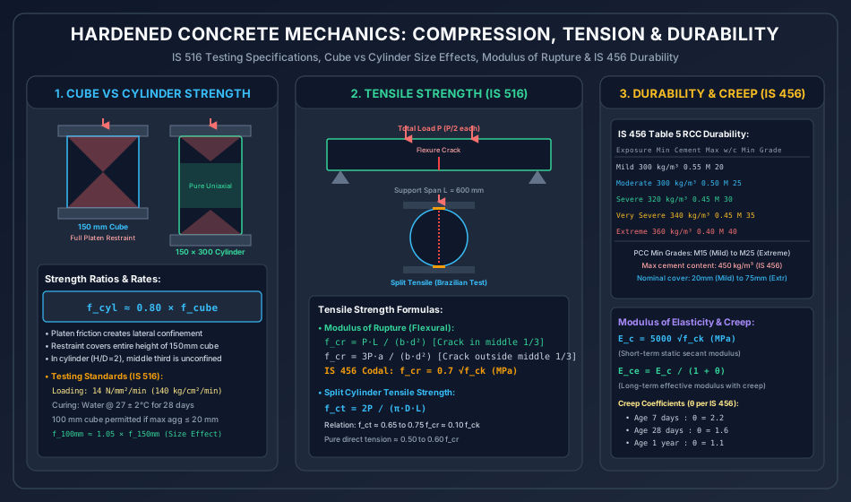
Platen Friction Restraint Effect:
- Steel platens possess a far higher elastic modulus () and lower Poisson's ratio () than concrete ().
- As concrete is compressed axially, it attempts to expand laterally. Frictional shear forces at the platen-concrete contact interfaces strongly grip the ends, preventing lateral expansion.
- This friction creates a triaxial state of compressive stress that forms rigid, uncracked pyramidal cones ( apex angle) extending inward from each platen.
-
Failure Mechanics:
- In a cube (height-to-width ratio ), the opposing restraint cones overlap completely across the mid-height. The entire cube is in a state of confined triaxial compression, artificially boosting the apparent failure load!
- In a cylinder (), the restraint cones extend inward only from each end. The central gauge zone is completely free from platen shear restraint, failing in pure, true uniaxial compression through vertical cleavage cracks.
-
Codal Conversion Ratio:
(For high-strength concretes , the ratio rises to due to lower transverse strain and brittle matrix behavior).
-
Specimen Size Effect: Larger specimens contain a higher statistical probability of micro-flaws and Griffith crack initiators:
5.3 Concrete Maturity Concept (Nurse-Saul Equation)
Strength gain of concrete is a function of both curing time and temperature. Maturity () integrates the temperature-time history:
Where:
- ()
6. Tensile Strength & Modulus of Rupture (IS 516)
Concrete is inherently weak in tension; its tensile strength ranges from only of its compressive strength. Because direct uniaxial tension tests are notoriously difficult to conduct without eccentric gripping stresses, two indirect tensile methods are standardized:
6.1 Flexural Tensile Strength (Modulus of Rupture, )
- Apparatus: Concrete beam prism of tested on a span (or on a span).
- Loading: Subjected to symmetrical two-point loading at the third points (pure bending zone between load points with zero transverse shear). Loading rate: for beams.
- Governing Equations (IS 516):
- Case A: Crack occurs within the middle third of the span (): Where is total failure load, is support span (), is width (), and is depth ().
- Case B: Crack occurs outside the middle third but within of the span (): Where is the distance from the crack to the nearer support.
- Case C: Crack occurs outside middle third by (): The test result is invalid and must be discarded.
- IS 456:2000 Characteristic Formula:
6.2 Brazilian Splitting Tensile Strength () (IS 516 Part 1 Sec 2 / ASTM C496)
- Principle: A standard concrete cylinder is placed horizontally between the platens of a compression machine. Compressive line loads are applied along two diametrically opposite generators through narrow plywood packing strips ( thick, wide).
- Stress Mechanics: Under the line load , theory of elasticity dictates that a uniform, horizontal transverse tensile stress field is induced across almost the entire vertical diameter plane.
- Formula: Where is ultimate compressive failure load, is diameter (), and is length ().
- Tensile Hierarchy:
7. Elastic Modulus, Creep, Shrinkage & Durability (IS 456)
7.1 Modulus of Elasticity ()
The stress-strain curve of concrete is non-linear. IS 456 specifies the short-term static secant modulus of elasticity evaluated at a stress level of approximately one-third of characteristic strength:
(Note: Actual measured modulus may vary by depending on aggregate stiffness and moisture content).
7.2 Creep of Concrete & Effective Modulus ()
Creep is the time-dependent, irreversible progressive deformation of concrete under sustained structural loading.
- Creep Coefficient (): Ratio of ultimate creep strain () to instantaneous elastic strain ():
- IS 456:2000 Statutory Values of :
- Loaded at 7 days:
- Loaded at 28 days:
- Loaded at 1 year:
- Long-Term Effective Modulus of Elasticity (): Used directly in long-term structural deflection and prestress loss calculations.
7.3 Drying Shrinkage
Concrete contracts upon losing moisture from its capillary and gel pores. In the absence of specific test data, IS 456 Cl. 6.2.4 specifies a nominal ultimate drying shrinkage strain of:
7.4 IS 456:2000 Durability Mandates (Tables 3, 4, and 5)
Durability is the ability of concrete to withstand its environmental exposure conditions without deterioration over its intended service design life ().
| Environmental Exposure Condition (IS 456 Cl. 8.2.2.1) | Physical Environment Description | Minimum Cement Content (RCC) | Maximum Free w/c Ratio (RCC) | Minimum Grade of Concrete (RCC) | Nominal Cover to Steel (mm) |
|---|---|---|---|---|---|
| Mild | Completely sheltered from rain; non-aggressive internal dry air. | M 20 | |||
| Moderate | Concrete exposed to severe rain; completely immersed in plain water; buried in non-aggressive soil. | M 25 | |||
| Severe | Severe rain with alternate wetting/drying; exposed to sea water spray; coastal structures. | M 30 | |||
| Very Severe | In contact with aggressive seawater/subsoil water; exposed to sulfate soil; freezing conditions while wet. | M 35 | |||
| Extreme | Direct contact with liquid aggressive chemicals; tidal splash zones in marine environments. | M 40 |
- Plain Concrete (PCC) Minimum Grades: M15 (Mild to Moderate), M20 (Severe to Very Severe), M25 (Extreme).
- Upper Statutory Cement Limit: Maximum permissible cement content (all exposures) to prevent excessive thermal cracking and autogenous shrinkage.
8. Solved Numerical Problem 1: Compacting Factor & Powers' Gel-Space Ratio
Problem Statement
A laboratory mix proportioned with and 43 Grade Ordinary Portland Cement is evaluated for fresh consistency and hardened compressive capacity:
- In a standard Compacting Factor test, the empty cylinder weighs . The mass of the cylinder containing partially compacted concrete (after free fall) is . When refilled and vibrated to complete compaction, the gross mass is . Compute the Compacting Factor () and classify its workability.
- Assuming standard moist curing at achieves an degree of hydration () at 28 days, calculate Powers' Gel-Space Ratio ().
- Compute the theoretical 28-day compressive strength () using Powers' equation and evaluate the strength gain if the degree of hydration reaches ().
Step-by-Step Analytical Solution
Step 1: Compacting Factor ()
- Mass of empty cylinder: .
- Net mass of partially compacted concrete:
- Net mass of fully compacted concrete:
- Compacting Factor:
Workability Classification: A Compacting Factor of falls squarely in the Medium Workability range (), corresponding to a standard slump of approximately , suitable for normal reinforced concrete slabs and beams.
Step 2: Powers' Gel-Space Ratio () at
Powers' formulation for gel-space ratio is:
Given and :
- Numerator:
- Denominator:
- Gel-Space Ratio:
Step 3: Theoretical Compressive Strength ()
Using Powers' theoretical strength equation:
(This represents the intrinsic potential paste strength under pure frictionless confinement).
Step 4: Strength Gain at
- New Gel-Space Ratio:
- New Compressive Strength:
- Percentage Strength Increase:
9. Solved Numerical Problem 2: Flexural Tensile & Split Tensile Calculations
Problem Statement
A hardened concrete investigation per IS 516 evaluates the tensile parameters of a structural batch:
- A standard flexure test beam of dimensions , , and total length is placed on rollers spanning . Symmetrical two-point loading is applied at the third points until failure occurs at a total load of . The tensile crack initiates on the bottom tension face at a distance of from the nearer support. Compute the Modulus of Rupture () and determine the nominal characteristic compressive strength () implied by IS 456.
- A companion standard cylinder of diameter and length is subjected to a Brazilian splitting test, failing under a total compressive line load of . Calculate the splitting tensile strength () and evaluate the ratio .
Step-by-Step Analytical Solution
Step 1: Modulus of Rupture () Evaluation
- Span .
- Third point locations: and .
- Middle third region: Between and from support.
- Distance of fracture line from nearer support: .
Check Fracture Location: Since , the failure crack occurred strictly within the middle third of the span. Per IS 516, the standard pure bending formula applies:
Substituting the numerical values:
- Section Modulus:
- Maximum Bending Moment:
Step 2: Implied Characteristic Compressive Strength ()
According to IS 456:2000 Cl. 6.2.2:
(Indicates high-strength concrete).
Step 3: Splitting Tensile Strength ()
Using the Brazilian cylinder line-load formula:
Given:
Step 4: Tensile Strength Ratio
(Consistent with experimental findings where splitting tensile strength represents of modulus of rupture due to the steep non-linear strain gradient across bending prisms).
10. Solved Numerical Problem 3: Elastic Modulus, Creep Kinetics & Long-Term Deflection
Problem Statement
An M30 grade reinforced concrete bridge girder is cast and cured under standard site conditions:
- Compute the short-term static secant modulus of elasticity () per IS 456:2000.
- Determine the long-term effective modulus of elasticity () if full permanent structural dead load is applied when the concrete age is:
- Case A: 7 days
- Case B: 28 days
- Case C: 1 year
- If an initial elastic dead load deflection of is measured immediately after prestressing/loading at an age of 28 days, calculate the total cumulative long-term deflection () and the incremental time-dependent creep deflection () after several years.
Step-by-Step Analytical Solution
Step 1: Short-Term Elastic Modulus ()
For M30 concrete, . Using IS 456 Cl. 6.2.3.1:
Step 2: Long-Term Effective Modulus ()
The effective modulus is computed using:
-
Case A: Loaded at 7 days ():
-
Case B: Loaded at 28 days ():
-
Case C: Loaded at 1 year ():
Step 3: Long-Term Deflection Analysis (Loaded at 28 days)
Because deflection is inversely proportional to the flexural stiffness ():
Given and :
The incremental time-dependent creep deflection alone is:
Engineering Conclusion: Creep deformation increases the initial deflection by (), demonstrating why neglecting creep causes serviceability failures (sagging floors, jamming doors, partition cracking).
11. Common Misconceptions, Pitfalls & Field Traps
-
The Slump Test Boundary Trap:
- The Trap: Attempting to use the slump test to characterize very dry concrete (e.g., pavement slipform mixes) or self-compacting concrete (SCC).
- The Reality: For zero-slump mixes (), the slump is uniformly regardless of actual compactability (use Vee-Bee or Compacting Factor). For SCC, the cone collapses completely; workability must be measured via Slump Flow () and V-Funnel time.
-
Cube vs. Cylinder Equivalence Myth:
- The Trap: Assuming an M30 grade mix yields on standard cylinders.
- The Reality: M30 designates a cube characteristic strength of . A companion cylinder will test at only ! Confusing cylinder and cube values leads to unwarranted rejection of compliant foreign or domestic mixes.
-
Flexural Modulus of Rupture vs. Direct Tensile Strength:
- The Trap: Using to calculate direct tensile crack resistance of water retaining walls.
- The Reality: Modulus of rupture is an elastic fictitious stress that overestimates true uniaxial tensile strength by because concrete experiences plastic yielding in the extreme tensile fibers before brittle rupture. For direct tension (IS 3370 liquid storage design), use .
-
Datum Temperature in Maturity Calculations:
- The Trap: Using as the baseline datum temperature for concrete maturity.
- The Reality: In the Nurse-Saul equation, hydration of Portland cement does not cease at ; it continues down to (). The datum must be taken strictly as .
-
Maximum Cement Limit Violation:
- The Trap: Believing that adding more cement beyond always improves durability.
- The Reality: IS 456 Cl. 8.2.4.2 strictly caps cementitious content at . Excess cement causes high hydration thermal gradients, extreme autogenous and drying shrinkage, and severe thermal cracking that destroys durability.
12. Multi-Exam Comparative Summary & High-Yield Facts Table
| Parameter / Topic | GATE CE Focus | UPSC ESE Focus | SSC JE / State AE Focus | RRB JE Focus |
|---|---|---|---|---|
| Slump Cone Dimensions | Top , Bottom , Height . | 4 layers, 25 tamps; rod . | Height: ; Top dia: ; Bottom: . | Cone height: (). |
| Compacting Factor () | Formula ; sensitivity in low workability (). | Cylinder dimensions: ; two hoppers. | Range for normal concrete: . | Ratio: Partially to fully compacted. |
| Cube vs Cylinder Ratio | Platen confinement mechanics ( cones); . | Ratio approaches for high strength (). | Factor: or . | Cylinder is weaker ( of cube). |
| Modulus of Rupture () | Derivation of ; IS 456 codal . | Beam dimensions: , span . | Formula: (Direct formula questions). | Value of flexural tensile strength. |
| Split Tensile Strength | Formula ; ratio . | Plywood strip dimensions ( thick, wide). | Cylinder tested horizontally under compression. | Formula: . |
| Elastic Modulus & Creep | ; effective modulus . | Creep coefficients: (7d), (28d), (1yr). | (Most repeated question). | Creep value after 28 days (). |
| IS 456 Durability (RCC) | Min cement (), Max w/c (), Min grades (M20-M40). | Environmental definitions (Severe = sea spray; Extreme = tidal). | Min RCC grade: M20 (Mild), M30 (Severe). | Minimum grade for RCC: M20. |
| Bleeding & Segregation | Capillary bleed channels; reduction of rebar bond (). | Laitance removal; drop height limit (). | Water rising to surface (Bleeding); Separation (Segregation). | Term for separation of aggregates (Segregation). |
13. Comprehensive Glossary of Technical Terms
- Workability: The property of fresh concrete determining the ease and homogeneity with which it can be mixed, placed, compacted, and finished.
- True Slump: Symmetrical subsidence of the concrete cone without breaking or shear failure.
- Shear Slump: Asymmetrical failure where the upper portion of the slumped cone slips down an inclined shear plane, denoting lack of internal cohesion.
- Compacting Factor: The ratio of the mass of concrete compacted by standard gravitational fall to the mass of the same concrete fully compacted by mechanical means.
- Vee-Bee Seconds (): The time in seconds required for a slumped cone of concrete to be transformed into a level cylindrical surface under standardized table vibration.
- Segregation: The mechanical separation of coarse aggregate particles from the mortar matrix during handling, placing, or compacting.
- Bleeding: The upward migration of free water to the surface of freshly placed concrete caused by gravity settlement of solid constituents.
- Laitance: A weak, porous scum consisting of water, cement fines, and impurities that forms on the top surface of bleeding concrete.
- Abram's Law: An empirical law stating that for full compaction, concrete compressive strength is inversely proportional to the water-cement ratio.
- Powers' Gel-Space Ratio (): The ratio of the solid volume of hydrated cement gel to the total volume available (gel volume capillary pore volume).
- Modulus of Rupture (): The nominal maximum fiber stress at failure in a standard unreinforced concrete beam tested under symmetrical third-point flexure ().
- Split Tensile Strength (): The indirect tensile strength obtained by compressing a standard cylinder along two diametrically opposite line generators ().
- Creep Coefficient (): The ratio of ultimate time-dependent creep strain to initial elastic strain under sustained load.
- Nurse-Saul Maturity: An empirical parameter defined as the product of time and temperature above a datum of characterizing concrete strength gain.
14. References & Standard Codes
- Bureau of Indian Standards (BIS):
- IS 456:2000 — Plain and Reinforced Concrete — Code of Practice (Fourth Revision).
- IS 516:1959 / 2021 — Hardened Concrete — Methods of Test for Strength of Concrete.
- IS 1199 (Parts 1 to 7) — Fresh Concrete — Methods of Sampling, Testing and Analysis.
- IS 3370 (Part 1):2009 — Code of Practice for Concrete Structures for the Storage of Liquids.
- Neville, A. M. (2011). Properties of Concrete (5th Edition). Pearson Education.
- Shetty, M. S., & Jain, A. K. (2019). Concrete Technology: Theory and Practice (8th Edition). S. Chand Publishing.
- Mehta, P. K., & Monteiro, P. J. M. (2014). Concrete: Microstructure, Properties, and Materials (4th Edition). McGraw-Hill Education.