Highway Materials & Testing: Subgrade Soils, Aggregates, Bitumen Characterization & Marshall Mix Design
In this chapter (1 topics)
On this page
- 1. Title & Authoritative References
- 2. Prerequisites & Learning Objectives
- Prerequisites
- Learning Objectives
- 3. Subgrade Soil Engineering & Characterization
- 3.1 Soil Classification for Highways
- 3.2 California Bearing Ratio (CBR) Test (IS 2720 Part 16)
- 3.3 Plate Bearing Test & Modulus of Subgrade Reaction (k) (IS 9214)
- 4. Road Aggregates: Mechanical Properties & Testing
- 4.1 Mechanical Quality Test Suite (IS 2386 Part 4)
- 4.2 Particle Shape Tests (IS 2386 Part 1)
- 4.3 Durability, Polishing, and Adhesion Tests
- 5. Bituminous Binders: Chemistry & Characterization
- 5.1 Viscosity Grading System (IS 73:2013)
- 5.2 Laboratory Characterization Tests
- 6. Marshall Mix Design Technology
- 6.1 Specimen Fabrication and Testing
- 6.2 Volumetric Phase Relationships
- 6.3 Optimum Binder Content (OBC) Determination
- 7. Analytical Derivations
- Derivation 1: Theoretical Maximum Specific Gravity (Gmm)
- Derivation 2: Voids in Mineral Aggregate (VMA)
- Derivation 3: Plate Bearing Scaling (k1 a1 = k2 a2)
- 8. Solved Numerical Example 1: CBR & Plate Bearing Subgrade Mechanics
- Problem Statement
- Step-by-Step Analytical Solution
- 9. Solved Numerical Example 2: Aggregate Mechanical Testing Suite
- Problem Statement
- Step-by-Step Analytical Solution
- 10. Solved Numerical Example 3: Marshall Mix Volumetric Design
- Problem Statement
- Step-by-Step Analytical Solution
- 11. Common Misconceptions & Exam Traps
- 1. CBR Standard Loads: 2.5 mm vs 5.0 mm
- 2. Plate Bearing Modulus Scaling: Radius Inverse Relation
- 3. Shape Gauges: Flakiness vs. Elongation Multipliers
- 4. Marshall VMA Calculation Basis
- 12. Quick Revision Summary & Formula Sheet
- 13. References & Standard Codes
1. Title & Authoritative References
- Indian Roads Congress (IRC) & Bureau of Indian Standards (BIS):
- IRC: 37-2018: Guidelines for the Design of Flexible Pavements (Fourth Revision)
- IRC: 58-2015: Guidelines for the Design of Plain Jointed Rigid Pavements for Highways (Fourth Revision)
- IS 2720 (Part 16): 1987: Methods of Test for Soils: Laboratory Determination of CBR
- IS 9214: 1979: Method of Determination of Modulus of Subgrade Reaction (k-value) of Soils in Field
- IS 2386 (Parts 1 to 4): 1963: Methods of Test for Aggregates for Concrete (Particle Size and Shape, Estimation of Deleterious Materials, Specific Gravity and Voids, Mechanical Properties)
- IS 73: 2013: Paving Bitumen — Specification (Fourth Revision)
- IS 1201 to IS 1220: Methods for Testing Tar and Bituminous Materials (Penetration, Softening Point, Ductility, Viscosity, Flash and Fire Point)
- MoRTH (5th Revision): Specifications for Road and Bridge Works, Section 500 (Bases and Surface Courses), Ministry of Road Transport and Highways.
- Academic & International Standards:
- ASTM D6926 / ASTM D6927: Standard Practice for Preparation and Marshall Testing of Bituminous Mixtures
- Asphalt Institute MS-2: Asphalt Mix Design Methods, 7th Edition, Lexington, KY.
- Khanna, S.K., Justo, C.E.G., and Veeraragavan, A., Highway Materials and Pavement Testing, Nem Chand & Bros.
- Roberts, F.L., Kandhal, P.S., Brown, E.R., Lee, D.Y., and Kennedy, T.W., Hot Mix Asphalt Materials, Mixture Design, and Construction, NAPA Education Foundation.
2. Prerequisites & Learning Objectives
Prerequisites
- Soil Mechanics: Particle size distribution, Atterberg limits, compaction curves (OMC, MDD per IS 2720:7/8), Boussinesq elastic half-space stress distribution.
- Material Science: Viscoelasticity, Newtonian and non-Newtonian fluid rheology, temperature susceptibility, brittle-ductile transition.
- Phase Relations: Mass-volume phase diagrams, bulk specific gravity (), theoretical maximum specific gravity (), void ratios.
Learning Objectives
- Characterize subgrade soils via the California Bearing Ratio (CBR) test; apply zero-correction to load-penetration curves and execute repeat test protocols.
- Formulate the Plate Bearing Test (IS 9214); evaluate the Modulus of Subgrade Reaction (), and apply Boussinesq plate size () and moisture saturation corrections.
- Master laboratory testing methodologies for road aggregates: Aggregate Crushing Value (ACV), Aggregate Impact Value (AIV), Los Angeles Abrasion Value (LAAV), Flakiness Index (FI), Elongation Index (EI), and Soundness.
- Classify paving bitumen per IS 73:2013 viscosity grades (VG-10 through VG-40); execute and interpret penetration, softening point (Ring & Ball), ductility, viscosity, and flash/fire tests.
- Derive and compute Marshall mix design volumetric parameters: Bulk specific gravity (), Theoretical maximum specific gravity (), Air Voids (), Voids in Mineral Aggregate (), and Voids Filled with Bitumen ().
- Determine the Optimum Binder Content (OBC) for bituminous concrete mixtures based on MoRTH stability, flow, and volumetric criteria.
3. Subgrade Soil Engineering & Characterization
The subgrade represents the compacted native soil bed supporting the entire superimposed pavement structure. Its structural capacity governs the required thickness of flexible and rigid pavement courses.
3.1 Soil Classification for Highways
- HRB / AASHTO Classification (A-1 to A-7): Classifies soils based on grain size distribution and Atterberg limits. Soils from A-1-a (well-graded gravel/stone) to A-3 (clean sand) provide excellent subgrade support, while A-6 and A-7 (plastic clays) exhibit high volume change, swelling potential, and poor drainage.
- Group Index (GI): Evaluates subgrade quality within an AASHTO group: where are parameters derived from the percentage passing the sieve, Liquid Limit (), and Plasticity Index (). Lower values () denote superior subgrades, whereas higher values () indicate poor subgrades.
3.2 California Bearing Ratio (CBR) Test (IS 2720 Part 16)
The CBR test evaluates the relative shearing resistance of a compacted subgrade soil under controlled moisture and surcharge conditions.
Test Protocol & Standard Specifications
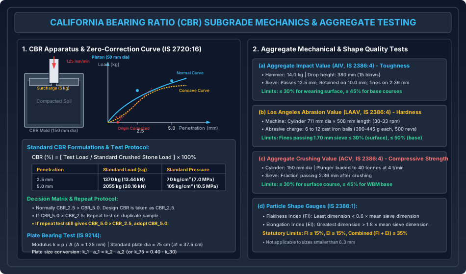
- Specimen Preparation: Soil compacted at Optimum Moisture Content (OMC) to Maximum Dry Density (MDD) in a cylindrical metallic mold ( internal diameter height, with detachable collar).
- Soaking: To simulate the worst seasonal monsoon saturation, the specimen is submerged in water for 4 days () with an annular surcharge weight of ( rings of ) placed on top to represent superimposed pavement weight. Swelling is monitored using a dial gauge.
- Penetration Mechanism: A hardened cylindrical steel plunger ( diameter, cross-sectional area ) is forced into the soil specimen at a constant strain rate of .
- Standard Reference Loads: Established from laboratory penetration tests on high-quality crushed California limestone rock:
| Plunger Penetration Depth | Standard Resistance Load () | Standard Unit Pressure () |
|---|---|---|
| () | () | () |
| () | () | () |
| () | ()** | ()** |
| () | ()** | ()** |
Load-Penetration Curve Zero-Correction
The standard load-penetration curve is convex upward throughout. However, if the top surface is soft, uncompacted, or irregular, the initial curve exhibits a concave upward profile.
- A tangent is drawn to the steepest point of the curve and extended downward to intersect the horizontal penetration axis.
- The intersection point () is designated as the corrected virtual origin.
- Penetrations of and must be measured from this corrected origin ( and ).
Calculation & Statutory Decision Protocol
[!IMPORTANT] CBR Selection & Retest Rule (IS 2720 Part 16):
- Under standard soil mechanics, . In this case, is reported as the design CBR.
- If , the test must be repeated on a fresh duplicate specimen.
- If the repeat test confirms , the higher value () is adopted for design.
3.3 Plate Bearing Test & Modulus of Subgrade Reaction () (IS 9214)
Used extensively in rigid pavement design (IRC: 58) to quantify subgrade support as a Winkler elastic spring foundation:
where is the mean contact pressure required to produce a standard settlement ().
Plate Size Correction
The standard test utilizes a circular steel bearing plate of diameter (). When smaller plates (e.g., ) are utilized in restricted trenches, Boussinesq elastic settlement theory () establishes that contact pressure :
4. Road Aggregates: Mechanical Properties & Testing
Mineral aggregates constitute of the weight of bituminous mixtures and of granular base courses (WBM/WMM), serving as the primary load-bearing skeleton.
4.1 Mechanical Quality Test Suite (IS 2386 Part 4)
-
Aggregate Crushing Value (ACV) — Resistance to Compressive Crushing:
- Evaluates aggregate crushing strength under static compressive loading.
- Fraction passing and retained on IS sieve is loaded into a diameter steel cylinder.
- Compressive load applied via universal testing machine up to () at a uniform rate of .
- Crushed aggregate is sieved through a IS sieve: (MoRTH Criteria: for surface/wearing courses, for base/sub-base courses).
-
Aggregate Impact Value (AIV) — Resistance to Impact / Toughness:
- Evaluates resistance to sudden shattering impact from dynamic vehicular traffic.
- Fraction ( passing, retained) is placed in a cylindrical cup in 3 tamped layers.
- A hammer is dropped freely through a height of () for 15 blows at intervals of not less than .
- Sample sieved over a IS sieve: (MoRTH Criteria: for dense bituminous surfacing, for surface dressing/WBM, for sub-bases).
-
Los Angeles Abrasion Value (LAAV) — Resistance to Abrasion / Hardness:
- Combines rubbing action (attrition) with impact shattering (abrasion).
- Standard hollow steel cylinder ( internal diameter internal length) rotated at for (or for large gravel).
- Abrasive charge: 6 to 12 cast iron / steel balls (each weighing , diameter , total charge weight ).
- Material discharged and sieved over a IS sieve: (MoRTH Criteria: for wearing courses, for bituminous bases, for sub-bases).
4.2 Particle Shape Tests (IS 2386 Part 1)
Flaky and elongated particles fracture prematurely under roller compaction, induce segregation, and create excessive voids:
- Flakiness Index (FI):
- The percentage by weight of particles whose least dimension (thickness) is less than times () their mean sieve dimension:
- Evaluated using a standard metal thickness gauge with precision rectangular slots.
- Elongation Index (EI):
- The percentage by weight of particles whose greatest dimension (length) is greater than times () their mean sieve dimension:
- Evaluated using a standard length gauge with vertical pins.
- Statutory Limits:
- Individual limits: , .
- Combined limit: for high-performance Bituminous Concrete (BC) and Dense Bituminous Macadam (DBM). Shape tests are not applied to aggregate sizes smaller than .
4.3 Durability, Polishing, and Adhesion Tests
- Soundness Test (IS 2386 Part 5): Evaluates aggregate weather resistance against freeze-thaw cycles by subjecting samples to 5 alternate immersion and drying cycles in saturated sodium sulfate (, loss ) or magnesium sulfate (, loss ).
- Bitumen Stripping / Coating Test (IS 6241): Assesses aggregate-binder adhesion in water. Aggregates coated with bitumen are submerged in a water bath for . MoRTH mandates a minimum retained coating of .
5. Bituminous Binders: Chemistry & Characterization
Bitumen is a complex colloidal mixture of high-molecular-weight hydrocarbons (asphaltenes dispersed in maltenes/resins).
5.1 Viscosity Grading System (IS 73:2013)
The modern Indian specification classifies paving bitumen based on Absolute Viscosity at (representing maximum pavement operating temperatures during peak summer):
| Viscosity Grade | Absolute Viscosity at (Poise) | Kinematic Viscosity at (cSt, min) | Softening Point (, min) | Penetration at (, min) | Recommended Field Application |
|---|---|---|---|---|---|
| VG-10 | Cold climate paving, spraying, surface dressing | ||||
| VG-20 | Temperate climatic zones | ||||
| VG-30 | General paving (BC/DBM) for majority of India | ||||
| VG-40 | Heavy traffic corridors, toll plazas, intersections |
5.2 Laboratory Characterization Tests
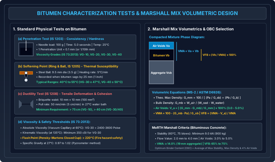
- Penetration Test (IS 1203): Measures bitumen consistency/hardness. A standard polished steel needle ( total load including carrier) penetrates the sample in a water bath for exactly . Penetration is recorded in units. (e.g., bitumen penetrates to ).
- Softening Point Test (Ring and Ball, IS 1205): Measures the temperature at which bitumen transitions from a semi-solid to a liquid state. Brass rings filled with bitumen are immersed in a liquid bath (distilled water or glycerin) heated at a constant rate of . A steel ball ( dia, ) placed on the sample sags down through the ring by () to trigger the softening temperature reading.
- Ductility Test (IS 1208): Evaluates tensile deformation and cohesive tensile strength. A standard briquette mold with a neck cross-section of () is pulled apart in a water bath at a uniform speed of (). The elongation distance in prior to ductile thread rupture is recorded. Paving bitumens require a ductility of (or for heavy VG-30/VG-40).
- Flash and Fire Point Test (Pensky-Martens Closed Cup, IS 1209): Determines temperature safety limits during heating and mixing.
- Flash Point: Lowest temperature at which bitumen vapor ignites momentarily in the presence of a test flame. (MoRTH minimum: ).
- Fire Point: Lowest temperature at which the material burns continuously for at least ( higher than flash point).
6. Marshall Mix Design Technology
Developed by Bruce Marshall (Mississippi Highway Dept) and standardized in ASTM D6926/D6927 and Asphalt Institute MS-2, the Marshall method balances structural stability against fatigue flexibility and durability.
6.1 Specimen Fabrication and Testing
- Cylindrical specimens of diameter () and height () are fabricated using of blended aggregates and bitumen heated to compaction temperature ().
- Compaction is executed with a Marshall drop hammer (, free fall) applying on each face for heavy traffic corridors ( for medium traffic).
- Specimens are submerged in a constant water bath at for .
- Tested in a Marshall breaking head loaded at a constant deformation rate of ():
- Marshall Stability: Peak compressive load registered in or .
- Marshall Flow: Total vertical plastic deformation recorded between zero load and peak stability, measured in units of or directly in .
6.2 Volumetric Phase Relationships
1. Specific Gravity of Combined Aggregate Blend ()
where are the weight percentages of individual aggregate fractions (coarse aggregate, fine aggregate, mineral filler) normalized to total aggregate weight (), and are their apparent specific gravities.
2. Theoretical Maximum Specific Gravity of Voidless Mixture ()
The density of the bituminous mixture if compressed to air voids (Rice specific gravity, ASTM D2041):
where is aggregate weight percentage by total mix (), is bitumen binder percentage, and is bitumen specific gravity ().
3. Bulk Specific Gravity of Compacted Specimen ()
where is dry specimen weight in air, is saturated surface-dry weight, and is submerged weight in water.
4. Percent Air Voids in Compacted Mix ( or )
The volume of air voids between coated particles expressed as a percentage of total specimen bulk volume:
5. Voids in Mineral Aggregate ()
The volume of intergranular void spaces between compacted aggregate particles, including both air voids and effective bitumen volume:
6. Voids Filled with Bitumen ()
The portion of the intergranular void space () filled with effective bitumen binder:
6.3 Optimum Binder Content (OBC) Determination
Trial specimens are prepared across a range of bitumen contents (e.g., ) and plotted on 5 standard design curves:
- Stability vs. Bitumen Content (exhibits a distinct peak).
- Flow Value vs. Bitumen Content (monotonically increases).
- Bulk Specific Gravity () vs. Bitumen Content (exhibits a distinct peak).
- Percent Air Voids () vs. Bitumen Content (monotonically decreases).
- Voids in Mineral Aggregate () vs. Bitumen Content (dips to minimum, then increases).
OBC Selection Rule:
The selected OBC is then verified to ensure all volumetric and strength parameters strictly satisfy MoRTH criteria.
MoRTH Design Acceptance Criteria (Bituminous Concrete)
| Marshall Parameter | MoRTH Specification Limit | Significance |
|---|---|---|
| Marshall Stability () | () | Prevents high-temperature rutting and shoving |
| Marshall Flow Value | ( units of ) | Flexibility check; prevents brittle cracking or rutting |
| Air Voids () | Lower causes bleeding; higher causes oxidation/raveling | |
| Voids in Mineral Aggregate () | (for nominal max aggregate) | Guarantees sufficient room for binder and air |
| Voids Filled with Bitumen () | Ensures durable aggregate coating and moisture seal |
7. Analytical Derivations
Derivation 1: Theoretical Maximum Specific Gravity ()
Consider a unit mass () of voidless bituminous mixture containing percent aggregate and percent bitumen by weight:
The total volume occupied by the solid constituents () equals the volume of aggregates plus volume of bitumen:
Dividing both sides by unit water density :
The theoretical maximum specific gravity is the total mass divided by the voidless volume:
Derivation 2: Voids in Mineral Aggregate ()
Let a compacted bituminous specimen have total bulk volume and total mass . By definition, is the percentage of total bulk volume occupied by voids between aggregate particles:
The volume occupied by the solid mineral aggregates is:
The bulk volume of the mixture is:
Dividing by :
Substituting into the definition:
Derivation 3: Plate Bearing Scaling ()
From Boussinesq elastic half-space theory, the uniform elastic surface settlement under a circular rigid plate of radius carrying contact pressure is:
where is the elastic modulus of the subgrade soil. Rearranging for contact pressure :
By definition of the modulus of subgrade reaction ():
Since subgrade modulus is an intrinsic physical soil property independent of plate size:
For two plates of radii and (or diameters and ):
8. Solved Numerical Example 1: CBR & Plate Bearing Subgrade Mechanics
Problem Statement
- A soaked laboratory California Bearing Ratio test on a highway subgrade soil produced the following proving ring load measurements:
- Penetration at :
- Penetration at : Determine the CBR values at both penetrations, explain the mandatory engineering decision protocol, and state the design CBR value.
- A field Plate Bearing Test (IS 9214) was performed using a smaller circular plate of diameter . The contact pressure required to induce a standard settlement was measured as .
- (a) Compute the modulus of subgrade reaction for the test plate ().
- (b) Determine the standard modulus of subgrade reaction () for the standard diameter plate.
- (c) If the unsoaked-to-soaked laboratory consolidation deflection ratio is , compute the final design modulus of subgrade reaction ().
Step-by-Step Analytical Solution
Part 1: California Bearing Ratio Determination
-
CBR at Penetration: Standard reference crushed stone load at .
-
CBR at Penetration: Standard reference crushed stone load at .
-
Engineering Decision & Repeat Protocol:
- Here, .
- Under IS 2720 Part 16, the test must be repeated on a duplicate compacted specimen.
- If the repeat test confirms that , the higher value is adopted:
Part 2: Plate Bearing Subgrade Modulus
-
Modulus for Plate (): Standard settlement .
-
Size Correction for Standard Plate (): Using Boussinesq scaling relation :
-
Moisture Saturation Correction (): Accounting for seasonal subgrade softening:
9. Solved Numerical Example 2: Aggregate Mechanical Testing Suite
Problem Statement
A laboratory quality control suite was executed on crushed basalt aggregates intended for a high-traffic highway wearing course:
- Aggregate Crushing Test: Sample weight . Weight passing the IS sieve after loading .
- Aggregate Impact Test: Sample weight . Weight passing the sieve after 15 blows of the hammer .
- Los Angeles Abrasion Test: Sample weight subjected to 500 revolutions with 12 abrasive spheres. Weight retained on sieve after test .
- Particle Shape Analysis: A representative sample of aggregates () yielded:
- Weight passing thickness gauge () .
- Weight retained on length gauge () .
Determine ACV, AIV, LAAV, Flakiness Index, Elongation Index, and Combined Shape Index. Evaluate compliance against MoRTH wearing course specifications.
Step-by-Step Analytical Solution
-
Aggregate Crushing Value (ACV):
Compliance: ceiling .
-
Aggregate Impact Value (AIV):
Compliance: surface limit .
-
Los Angeles Abrasion Value (LAAV): Weight of fines passing sieve .
Compliance: wearing limit .
-
Flakiness Index (FI) & Elongation Index (EI):
Overall Assessment: The aggregate sample satisfies all MoRTH strength, toughness, hardness, and shape criteria for Bituminous Concrete wearing courses.
10. Solved Numerical Example 3: Marshall Mix Volumetric Design
Problem Statement
A laboratory Bituminous Concrete specimen compacted with 75 blows on each face has the following composition by total mix weight:
- Aggregates ():
- Bitumen Binder (): (Specific gravity ) The aggregate blend consists of:
- Coarse Aggregate (): of total mix ()
- Fine Aggregate (): of total mix ()
- Mineral Filler (): of total mix ()
Laboratory measurements on the compacted specimen yield:
- Specimen mass in air ():
- Specimen submerged mass in water ():
- Saturated surface-dry mass ():
- Marshall Stability at :
- Marshall Flow Value:
- Compute the specific gravity of the aggregate blend () and the theoretical maximum specific gravity ().
- Determine the bulk specific gravity () and bulk volume of the compacted specimen.
- Calculate Percent Air Voids (), Voids in Mineral Aggregate (), and Voids Filled with Bitumen ().
- Evaluate compliance against MoRTH specifications for Bituminous Concrete.
Step-by-Step Analytical Solution
-
Specific Gravity of Combined Aggregate Blend (): Normalize aggregate fractions to aggregate weight:
-
Theoretical Maximum Specific Gravity ():
-
Bulk Specific Gravity () & Volume:
-
Volumetric Void Analysis:
- Air Voids ():
- Voids in Mineral Aggregate ():
- Voids Filled with Bitumen ():
-
MoRTH Compliance Scorecard:
- Stability:
- Flow Value: within
- Air Voids (): within
- VMA:
- VFB: within Final Verdict: The mix proportioning fully satisfies all statutory Indian highway engineering criteria.
11. Common Misconceptions & Exam Traps
[!WARNING]
1. CBR Standard Loads: vs
- Standard load at penetration is ().
- Standard load at penetration is ().
- Trap: Never use in the denominator of . If , you must explicitly mention the mandatory retest before adopting .
[!WARNING]
2. Plate Bearing Modulus Scaling: Radius Inverse Relation
- The modulus of subgrade reaction is inversely proportional to plate radius: .
- Trap: Applying direct proportionality () or area scaling (). A plate yields a higher -value than a standard plate: .
[!WARNING]
3. Shape Gauges: Flakiness vs. Elongation Multipliers
- Flakiness Gauge: Thickness ().
- Length Gauge: Length ().
- Trap: Inverting these factors ( for thickness and for length). Note also that neither test applies to particles passing the sieve.
[!WARNING]
4. Marshall Calculation Basis
- In , is the bulk specific gravity of the aggregate blend.
- Trap: Substituting effective specific gravity () or apparent specific gravity (). Using overestimates by ignoring aggregate binder absorption.
12. Quick Revision Summary & Formula Sheet
+---------------------------------------------------------------------------------------------------+
| HIGHWAY MATERIALS & MARSHALL TESTING FORMULA SHEET                                                |
+---------------------------------------------------------------------------------------------------+
| 1. Subgrade Characterization:                                                                     |
|    - CBR (%) = [ Corrected Test Load / Standard Crushed Rock Load ] * 100%                        |
|      * At 2.5 mm: Standard Load = 1370 kg (13.44 kN, 70 kg/cm^2)                                  |
|      * At 5.0 mm: Standard Load = 2055 kg (20.16 kN, 105 kg/cm^2)                                 |
|      * Decision: Design CBR = CBR_2.5 (if CBR_5.0 > CBR_2.5, retest; if still > adopt CBR_5.0)    |
|    - Modulus of Subgrade Reaction: k = p / Delta  (Delta = 1.25 mm)                               |
|      * Plate Size Scaling: k_1 * a_1 = k_2 * a_2   -->   k_75 = 0.40 * k_30                       |
|      * Saturation Correction: k_design = k_75 / (d_u / d_s)                                       |
+---------------------------------------------------------------------------------------------------+
| 2. Aggregate Mechanical Quality Limits (MoRTH):                                                   |
|    - Crushing Value (ACV, 40 t, 2.36 mm sieve):     <= 30% (Surface), <= 45% (Base)               |
|    - Impact Value (AIV, 14 kg, 380 mm, 15 blows):   <= 24-30% (Surface), <= 45% (Base)            |
|    - Abrasion Value (LAAV, 500 revs, 1.7 mm sieve): <= 30% (Surface), <= 50% (Base)               |
|    - Flakiness Index (FI, thickness < 0.6 mean):    <= 15%                                        |
|    - Elongation Index (EI, length > 1.8 mean):      <= 15%  |  Combined (FI + EI) <= 35%          |
|    - Soundness Loss (5 cycles): Na2SO4 <= 12%  |  MgSO4 <= 18%                                    |
|    - Bitumen Coating / Stripping Resistance:        >= 95%                                        |
+---------------------------------------------------------------------------------------------------+
| 3. Bitumen Physical Characterization (IS 73:2013):                                                |
|    - Penetration (100 g, 5 s, 25 deg C): 1 unit = 0.1 mm  (VG-30 >= 45 dmm)                       |
|    - Softening Point (Ring & Ball, 9.5 mm ball): Sag = 25 mm  (VG-30 >= 47 deg C)                  |
|    - Ductility (27 deg C, 5 cm/min): Briquette waist 10x10 mm  (VG-30 >= 40 cm, VG-10 >= 75 cm)    |
|    - Absolute Viscosity at 60 deg C: VG-10 (800-1200 P), VG-30 (2400-3600 P), VG-40 (3200-4800 P) |
|    - Flash Point (Pensky-Martens Closed Cup): > 220 deg C                                         |
+---------------------------------------------------------------------------------------------------+
| 4. Marshall Mix Volumetrics:                                                                      |
|    - Blend Bulk Sp. Gr.:   100 / G_sb = SUM( P_i / G_i )                                          |
|    - Theo. Max Density:    G_mm = 100 / [ (Pa / G_sb) + (Pb / G_b) ]                               |
|    - Bulk Density:         G_mb = W_air / (W_SSD - W_water)                                       |
|    - Air Voids:            V_a = [ (G_mm - G_mb) / G_mm ] * 100%   [Criteria: 3.0% - 5.0%]        |
|    - Voids in Mineral Agg: VMA = 100 - [ (G_mb * Pa) / G_sb ]      [Criteria: >= 14.0%]           |
|    - Voids Filled Bitumen: VFB = [ (VMA - V_a) / VMA ] * 100%      [Criteria: 65% - 75%]          |
|    - Marshall Stability:   >= 9.0 kN  |  Marshall Flow: 2.0 - 4.0 mm                              |
+---------------------------------------------------------------------------------------------------+
13. References & Standard Codes
- Bureau of Indian Standards (BIS):
- IS 2720 (Part 16): 1987 (Reaffirmed 2017): Laboratory Determination of CBR, New Delhi.
- IS 9214: 1979 (Reaffirmed 2016): Determination of Modulus of Subgrade Reaction, New Delhi.
- IS 2386 (Parts 1-4): 1963: Testing of Aggregates for Concrete, New Delhi.
- IS 73: 2013: Paving Bitumen — Specification (4th Revision), New Delhi.
- Ministry of Road Transport and Highways (MoRTH):
- Specifications for Road and Bridge Works (5th Revision), Indian Roads Congress, 2013.
- Primary Textbooks:
- Khanna, S.K., Justo, C.E.G., and Veeraragavan, A., Highway Materials and Pavement Testing, 5th Ed., Nem Chand & Bros.
- Asphalt Institute, MS-2: Asphalt Mix Design Methods, 7th Edition, Lexington, KY.