Highway Geometric Design: Cross-Section Elements, Sight Distances, Horizontal & Vertical Alignment (IRC 73 / IRC 86)
In this chapter (1 topics)
On this page
- 1. Title & Authoritative References
- 2. Prerequisites & Learning Objectives
- Prerequisites
- Learning Objectives
- 3. Highway Cross-Section Elements & Drainage Camber
- 3.1 Right-of-Way, Roadway, and Carriageway Elements
- 3.2 Transverse Drainage Camber (Cross-Slope)
- 4. Sight Distance Dynamics
- 4.1 Perception-Reaction Dynamics: The PIEV Theory
- 4.2 Stopping Sight Distance (SSD)
- 4.3 Overtaking Sight Distance (OSD)
- 4.4 Intermediate Sight Distance (ISD) & Headlight Sight Distance (HSD)
- 5. Horizontal Alignment Engineering: Super-Elevation Mechanics
- 5.1 Centrifugal Force and Equilibrium Equations
- 5.2 Limits of Stability: Skidding vs. Overturning
- 5.3 IRC Super-Elevation Design Procedure (IRC: 73 / IRC: 38)
- 6. Extra-Widening & Transition Curve Geometry
- 6.1 Extra-Widening on Horizontal Curves (We)
- 6.2 Transition Curve Geometry: The Clothoid Spiral
- 6.3 Setback Distance (m) on Obstructed Horizontal Curves
- 7. Vertical Alignment Engineering: Gradients & Vertical Curves
- 7.1 Classification of Gradients
- 7.2 Grade Compensation on Horizontal Curves
- 7.3 Summit (Crest) Vertical Curves
- 7.4 Valley (Sag) Vertical Curves
- 8. Analytical Derivations
- Derivation 1: Equilibrium Super-Elevation & IRC Design Coefficient
- Derivation 2: Mechanical Extra-Widening (Off-Tracking)
- Derivation 3: Shift of a Circular Curve (S)
- 9. Solved Numerical Example 1: SSD & OSD Analysis
- Problem Statement
- Step-by-Step Analytical Solution
- 10. Solved Numerical Example 2: Horizontal Curve & Super-Elevation Design
- Problem Statement
- Step-by-Step Analytical Solution
- 11. Solved Numerical Example 3: Vertical Curve Alignment
- Problem Statement
- Step-by-Step Analytical Solution
- 12. Common Misconceptions & Exam Traps
- 1. Friction Coefficients: Longitudinal vs. Lateral
- 2. The 75% Speed Factor in Step 1 of Super-Elevation Design
- 3. Single-Lane vs. Two-Lane SSD Requirements
- 4. Grade Compensation Constraints
- 5. Summit vs. Valley Curve Sight Heights
- 13. Quick Revision Summary & Formula Sheet
- 14. References & Standard Codes
1. Title & Authoritative References
- Indian Roads Congress Standard Codes:
- IRC: 73-1980: Geometric Design Standards for Rural (Non-Urban) Highways
- IRC: 86-1983: Geometric Design Standards for Urban Roads in Plains
- IRC: 38-1988: Guidelines for the Design of Horizontal Curves for Highways and Design Tables
- IRC: SP: 23-1993: Vertical Curves for Highways
- IRC: SP: 73-2018 / IRC: SP: 84-2019 / IRC: SP: 87-2019: Manuals of Specifications & Standards for Two-Laning, Four-Laning, and Six-Laning of Highways
- MoRTH (5th Revision): Specifications for Road and Bridge Works, Ministry of Road Transport and Highways, India.
- Academic Authorities:
- Khanna, S.K., Justo, C.E.G., and Veeraragavan, A., Highway Engineering, 10th Edition, Nem Chand & Bros.
- Kadiyali, L.R., Traffic Engineering and Transportation Planning, Khanna Publishers.
- Garber, N.J. and Hoel, L.A., Traffic and Highway Engineering, Cengage Learning.
- AASHTO, A Policy on Geometric Design of Highways and Streets ("Green Book"), 7th Edition.
2. Prerequisites & Learning Objectives
Prerequisites
- Newtonian Particle Mechanics: Centrifugal acceleration , normal force resolution on inclined planes, static and kinetic friction mechanics ().
- Integral Calculus & Geometry: Curvature , spiral clothoid parametric coordinates, second-order polynomial parabolic profiles.
- Kinematics of Motion: Uniform acceleration relationships (, ).
Learning Objectives
- Quantify highway cross-sectional elements (right-of-way, roadway width, carriageway width, shoulders, kerbs, and medians) in strict accordance with IRC 73 and IRC 86.
- Formulate and compute transverse drainage camber (parabolic, straight-line, composite) across distinct pavement surfaces and precipitation zones.
- Analyze human-vehicular perception-braking dynamics using PIEV theory to determine Stopping Sight Distance (SSD), Overtaking Sight Distance (OSD), Intermediate Sight Distance (ISD), and Headlight Sight Distance (HSD).
- Derive the fundamental horizontal equilibrium equation () and execute the 4-step Indian Roads Congress (IRC) super-elevation design protocol.
- Formulate mechanical and psychological extra-widening (), spiral transition curve design () via dynamic, comfort, and geometric criteria, and setback distance () on obstructed horizontal curves.
- Design vertical alignments: calculate ruling, limiting, and exceptional gradients; apply horizontal curve grade compensation; and compute summit and valley curve lengths for sight distance and passenger dynamic comfort.
3. Highway Cross-Section Elements & Drainage Camber
Highway geometric design coordinates the visible features of the roadway with vehicular performance, human physiological factors, and traffic volumes to provide safe, expeditious, and economical movement of goods and passengers.
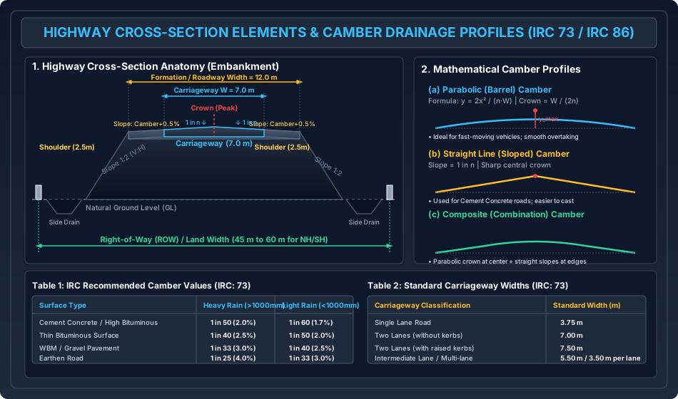
3.1 Right-of-Way, Roadway, and Carriageway Elements
- Right-of-Way (ROW) / Land Width: The designated strip of land acquired and reserved by the highway authority for construction, future capacity widening, roadside drainage, utility corridors, and environmental buffer zones.
- For National Highways (NH) and State Highways (SH) in open, rural plain/rolling terrain, standard ROW ranges between (normal) to (exceptional).
- Building lines and control lines are demarcated beyond the ROW boundaries to prevent haphazard roadside commercial encroachment and preserve sightline setbacks.
- Roadway Width (Formation Width): The combined horizontal width of the paved carriageway, paved/granular shoulders, and central median (if undivided embankment). It represents the top finished width of the embankment fill or bottom width of a cutting:
- Carriageway Width: The structural portion of the highway designated specifically for vehicular wheel passage. IRC: 73 defines standard carriageway widths based on operational traffic classifications:
| Carriageway Classification | Standard Width () | Operational Notes |
|---|---|---|
| Single Lane | Accommodates single vehicle clearance on each side | |
| Two Lanes (without raised kerbs) | Standard rural two-lane highway ( per lane) | |
| Two Lanes (with raised kerbs) | Urban/semi-urban setting; lateral kerb shying allowance ( per side) | |
| Intermediate Carriageway | Low-volume State Highways or Major District Roads (MDR) | |
| Multi-lane Divided Highway | per lane | Expressways, 4-lane ( or ), 6-lane () |
- Shoulders: Lateral strips adjacent to the outer edges of the carriageway designed to provide emergency vehicle stopping, lateral structural confinement to pavement base courses, and recovery space for straying vehicles.
- IRC: 73 specifies a minimum shoulder width of for rural highways.
- Shoulder cross-fall/slope must be steeper than the adjoining carriageway camber (subject to a minimum of for paved shoulders and for earth/gravel shoulders) to accelerate transverse surface runoff away from the road pavement.
- Medians (Traffic Separators): Physical barriers or depressed turf separators between opposing traffic streams on divided highways to eliminate head-on collisions, mitigate headlight glare, and accommodate future lane expansion.
- Desirable rural median width: ; absolute minimum on restricted bridges/culverts: (with crash barrier).
- Kerbs: Vertical or sloping stone/concrete dividers placed at the pavement boundary:
- Low/Mountable Kerb: Height , sloping face; allows vehicles to mount shoulder in emergencies.
- Semi-Barrier Kerb: Height ; prevents ordinary encroachment while permitting emergency access under low speeds.
- Barrier Kerb: Height ; steep face; prevents vehicles from leaving the carriageway (bridges, high embankments).
3.2 Transverse Drainage Camber (Cross-Slope)
Camber is the convex transverse slope provided to the carriageway surface to drain rainwater rapidly toward roadside ditches, preventing aquaplaning/hydroplaning, preserving pavement shear strength, and protecting subgrade moisture equilibrium.
Mathematical Profiles of Camber
- Parabolic (Barrel) Camber: The cross-section forms a continuous quadratic parabola with a smooth summit crown.
- Taking the origin at the pavement edge: where is the total carriageway width, is the inverse camber slope (), is the horizontal distance from the outer edge, and is the vertical elevation above the edge.
- The central crown height (maximum elevation at ) is:
- Advantage: Highly favorable for fast vehicular overtaking; provides a gentle, smooth profile across lanes.
- Straight-Line Camber: Two linear planar surfaces inclined at meeting at a sharp central apex:
- Advantage: Simple to construct with mechanical pavers; primarily specified for high-performance Cement Concrete (rigid) pavements.
- Composite Camber: A hybrid geometry featuring a central parabolic crown flanked by two straight-line sloping planes at the outer edges.
IRC Recommended Camber Specifications (IRC: 73)
The required cross-fall depends directly on the pavement surface permeability and the regional rainfall intensity:
| Road Surface Type | Heavy Rainfall Zone () | Light Rainfall Zone () |
|---|---|---|
| Cement Concrete (Rigid) / High Bituminous (BC/DBM) | () | () |
| Thin Bituminous Surfacing (Premix Carpet, Surface Dressing) | () | () |
| Water Bound Macadam (WBM) / Compacted Gravel | () | () |
| Earthen Subgrade / Earth Road | () | () |
4. Sight Distance Dynamics
Sight distance is the length of unobstructed roadway visible to a driver ahead along the centerline of the lane. Inadequate sight distance is a primary cause of high-speed collision fatalities.
4.1 Perception-Reaction Dynamics: The PIEV Theory
The total reaction time of a driver encompasses four sequential psychological and neuro-muscular stages:
- Perception (): Sensation of the optical stimulus (e.g., stationary hazard or oncoming vehicle) on the driver's retina and neural transmission to the brain.
- Intellection (): Cognitive processing, situational awareness, and understanding of the impending hazard.
- Emotion (): Emotional response (apprehension, fear, judgment) governing the chosen decision matrix.
- Volition (): Execution of the physical motor response (muscular actuation of the foot transferring from accelerator to brake pedal).
Under IRC standards:
- Total Reaction Time for SSD (): Taken as (encompassing percentile driver population variability under complex unexpected road situations).
- Total Reaction Time for OSD (): Taken as (since the driver is already actively tracking and anticipating the maneuver).
4.2 Stopping Sight Distance (SSD)
The minimum sight distance mandatory at all points along a highway to enable a vehicle traveling at design speed to brake to a complete stop prior to striking a stationary hazard.
Analytical Formulation of SSD
The total stopping distance comprises two independent kinematic regimes:
- Lag Distance (): Distance traveled during the driver's perception-reaction time at constant initial speed :
- Braking Distance (): Distance traversed under deceleration while braking. By the Work-Energy Theorem, kinetic energy equals work done against longitudinal tire-pavement friction and gravitational grade force:
For small highway angles , (where is longitudinal gradient in percent, for ascending, for descending):
where:
- = speed in , = speed in
- = coefficient of longitudinal friction (IRC specifies at , decreasing to at ).
Therefore, the Total Stopping Sight Distance is:
[!IMPORTANT] Carriageway Multipliers for SSD:
- Two-lane or Divided Carriageway: Operating vehicles face non-conflicting dedicated lane paths. Required Sight Distance .
- Single-Lane Carriageway with Two-Way Traffic: When two opposing vehicles approach head-on in the same lane, both must independently brake to a complete stop:
4.3 Overtaking Sight Distance (OSD)
The minimum open sight distance required on a two-way, two-lane undivided highway to permit the driver of a faster vehicle to overtake and pass a slower vehicle safely without colliding with an opposing vehicle appearing in the oncoming lane.
Kinematic Mechanics of Overtaking
The overtaking maneuver is analyzed in three discrete phases:
           |<-- d1 -->| |<----------- d2 ----------->|
Vehicle A: [A1] ----> [A2] ------------------------> [A3]
Vehicle B:            [B1] -------------> [B2]
Vehicle C:                                           [C2] <------------- [C1]
                                                     |<------- d3 ------->|
- Phase 1: Reaction and Speed Matching (): Vehicle A decelerates from its initial design speed to match the speed of the slower leading vehicle and travels behind it during reaction time : If is not explicitly measured, IRC: 73 stipulates:
- Phase 2: Acceleration and Lateral Passing ():
Vehicle A pulls into the opposing lane, accelerates past vehicle B, and safely returns to its lane.
- Initial minimum safe following distance between A and B ():
- During the overtaking time , vehicle B travels a distance .
- Vehicle A covers relative distance equal to :
- From kinematics under uniform lateral overtaking acceleration (): (IRC empirical acceleration values range from at to at ).
- Phase 3: Opposing Vehicle Approach (): During the overtaking duration , an oncoming vehicle C traveling at full highway design speed covers distance:
Therefore, the Total Overtaking Sight Distance on two-way undivided roads is:
[!NOTE] On a one-way divided highway (dual carriageway), no opposing vehicles exist; hence, and .
Overtaking Zones
Where terrain or economic constraints preclude providing continuous OSD, dedicated overtaking zones must be constructed:
- Minimum Length of Overtaking Zone:
- Desirable Length of Overtaking Zone:
4.4 Intermediate Sight Distance (ISD) & Headlight Sight Distance (HSD)
- Intermediate Sight Distance (ISD): Where providing full OSD is economically or topographically unfeasible, IRC permits providing ISD as a surrogate measure to offer limited, opportunistic overtaking opportunities:
- Headlight Sight Distance (HSD): The nighttime distance illuminated ahead by vehicle headlights (standard mounting height , beam spread angle upward ). By IRC criteria, the minimum headlight sight distance must equal the day stopping sight distance:
5. Horizontal Alignment Engineering: Super-Elevation Mechanics
When a vehicle negotiates a horizontal curve of radius at speed , an outward centrifugal acceleration acts at its center of gravity.
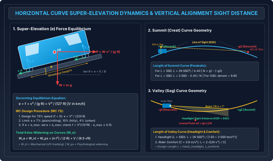
5.1 Centrifugal Force and Equilibrium Equations
The centrifugal force acting horizontally outward is:
The ratio is termed the Centrifugal Ratio or Impact Factor.
To resist this outward thrust without relying solely on tire friction, the transverse cross-section of the carriageway is tilted upward by raising the outer edge relative to the inner edge. This banking slope is the Super-Elevation ():
where is total vertical elevation rise and is pavement width.
Resolving forces parallel to the inclined road surface:
Resolving forces perpendicular to the road surface:
Substituting and dividing by :
Because highway super-elevation angles rarely exceed , and lateral tire friction . Thus, the product term , simplifying to the classic highway equilibrium relation:
where is super-elevation rate (), is coefficient of lateral friction (), is speed in , and is curve radius in meters ().
5.2 Limits of Stability: Skidding vs. Overturning
A vehicle on a flat unbanked curve () faces two distinct failure modes:
- Lateral Skidding: Occurs when centrifugal thrust exceeds maximum tire friction:
- Overturning (Rollover): Occurs when the moment of about outer wheels exceeds the stabilizing moment of weight : where is the wheel gauge and is the height of the center of gravity above the road.
- Safety Criterion: To guarantee skidding occurs prior to catastrophic overturning (giving the driver an auditory/tactile skid warning):
5.3 IRC Super-Elevation Design Procedure (IRC: 73 / IRC: 38)
Because highway mixed-traffic streams contain slow-moving bullock carts/tractors alongside high-speed cars, providing maximum super-elevation for full design speed would cause slow vehicles to slide down the inward slope. Hence, IRC mandates a rigorous 4-step compromise design protocol:
Step 1: Design for 75% Speed Neglecting Friction
To provide full passenger comfort for ordinary operating speeds, super-elevation is sized to balance the centrifugal force of of the design speed () purely by banking ():
Step 2: Check Maximum Super-Elevation Limit ()
Compare the calculated against the IRC statutory ceiling:
- Plain and Rolling Terrain:
- Hilly Terrain (not snow-bound):
- Urban Roads with Frequent Intersections:
- Decision:
- If : Adopt the computed . Friction is not mobilized under normal speeds.
- If : Cap super-elevation at (e.g., ) and proceed to Step 3.
Step 3: Check Lateral Friction Factor () at Full Design Speed
With super-elevation fixed at , evaluate the required lateral friction when vehicles traverse the curve at the full design speed :
- Decision:
- If : Adopt and . The curve geometry is fully verified and safe.
- If : The radius is structurally inadequate for speed . Proceed to Step 4.
Step 4: Speed Restriction ()
If realignment to a larger radius is unfeasible, fix and , and enforce a mandatory regulatory speed restriction:
6. Extra-Widening & Transition Curve Geometry
6.1 Extra-Widening on Horizontal Curves ()
When negotiating a curve, a long four-wheeled vehicle does not track cleanly; the rear rigid axle does not articulate and follows an inner path relative to the front steered wheels (off-tracking). Furthermore, drivers experience psychological strain and maintain larger lateral clearances.
Total extra-widening () consists of two components:
- Mechanical Widening (): Derived from the geometric off-tracking of the rear axle over a circular arc: where is the number of traffic lanes, is the vehicular wheelbase length (standard Indian commercial vehicle or ), and is the curve radius.
- Psychological Widening (): An empirical allowance formulated by IRC to account for driver steering difficulties, visual perspective distortion, and lateral sway at high speeds:
Thus, the Total Carriageway Width on Curve is:
[!TIP] IRC Application Rule:
- For , extra-widening is negligible and omitted.
- For , the entire is applied to the inner edge of the curve.
- For , is introduced equally along both the inner and outer edges ( each).
6.2 Transition Curve Geometry: The Clothoid Spiral
To eliminate abrupt lateral jerk, a transition curve with continuously varying curvature is introduced between the tangent straight line () and the circular curve ().
IRC specifies the Clothoid (Euler Spiral) as the ideal highway transition curve because its curvature is directly proportional to its traversed curve length :
This guarantees a uniform rate of increase of centrifugal acceleration:
Design Criteria for Length of Transition Curve ()
The design transition length is taken as the maximum computed from three independent criteria:
- Criterion 1: Allowable Rate of Change of Centrifugal Acceleration (Comfort / Jerk): where is in , in , and is the allowable radial jerk (). IRC empirical equation for :
- Criterion 2: Rate of Introduction of Super-Elevation:
Super-elevation is transitioned linearly at a design gradient of (IRC specifies in plain/rolling terrain, in hilly terrain).
- If pavement is rotated about the inner edge: Outer edge rises by full :
- If pavement is rotated about the centerline: Outer edge rises by and inner drops by :
- Criterion 3: IRC Empirical Formula:
- Plain and Rolling Terrain:
- Mountainous and Steep Terrain:
Shift of the Circular Curve ()
Introducing transition spirals requires shifting the original circular arc inward by distance to accommodate the spiral between tangent and circle:
The total required tangent distance from point of intersection (PI) becomes:
where is the total deflection angle of the curve.
6.3 Setback Distance () on Obstructed Horizontal Curves
The setback distance () is the minimum lateral clearance required between the road centerline and any roadside lateral obstruction (e.g., retaining wall, building, steep cut slope) on the inner side of a curve to ensure unobstructed line of sight equal to SSD.
- Case A: Length of Curve () Exceeds Sight Distance (): Let be the centerline radius, and be the lateral distance from the road centerline to the path of the driver's inner wheel line (typically for two-lane roads). The angle subtended by the sight distance arc at the curve center is: The required setback distance measured from the road centerline is: The setback measured from the inner edge of the pavement () is:
- Case B: Length of Curve is Less than Sight Distance (): The sight distance line intersects the tangents beyond the curve transitions:
7. Vertical Alignment Engineering: Gradients & Vertical Curves
Vertical alignment governs the longitudinal profile of the highway, comprising grade tangents connected by smooth vertical transition curves.
7.1 Classification of Gradients
- Ruling Gradient: The maximum gradient adopted in normal design practice to ensure heavy freight commercial vehicles maintain reasonable operating speeds without excessive mechanical strain.
- Limiting Gradient: A steeper gradient permitted over short, restricted stretches where topographical features render adopting the ruling gradient economically prohibitive.
- Exceptional Gradient: An extraordinary steep gradient permitted only in severe mountainous stretches for continuous lengths not exceeding .
- Minimum Gradient: The minimum longitudinal slope mandatory for uncurbed roads () or kerbed pavements () to facilitate longitudinal drainage of side channels.
IRC Standard Gradient Matrix (IRC: 73)
| Terrain Classification | Ruling Gradient | Limiting Gradient | Exceptional Gradient |
|---|---|---|---|
| Plain or Rolling | () | () | () |
| Mountainous Terrain (elevation ) | () | () | () |
| Steep Terrain | () | () | () |
7.2 Grade Compensation on Horizontal Curves
When a sharp horizontal curve occurs concurrently on a steep upgrade, commercial vehicles experience compound resistance: tractive grade resistance plus curve curve-drag resistance. To keep total tractive resistance within the ruling grade limit, the longitudinal grade must be relieved by Grade Compensation (GC):
where is the horizontal curve radius in meters.
[!IMPORTANT] IRC Statutory Caveats:
- Grade compensation is not applied on curves with radius (as curve resistance is negligible).
- The compensated gradient shall never be reduced below (if the uncompensated grade minus drops below , the design grade is fixed at ).
7.3 Summit (Crest) Vertical Curves
Summit curves are convex upward profiles connecting ascending and descending gradients. The algebraic difference in gradients is:
A simple square parabola () is universally adopted as the summit curve because of its constant rate of change of grade (), ensuring smooth centrifugal acceleration and ease of field setting out.
Summit Curve Length Formulations (Sight Distance Governing)
- Design for Stopping Sight Distance (SSD):
- Standard parameters: Driver eye height ; Obstacle height .
- Denominator factor: .
- Case 1: When Length of Curve Exceeds Sight Distance ():
- Case 2: When Length of Curve is Less than Sight Distance ():
- Design for Overtaking Sight Distance (OSD) or ISD:
- Standard parameters: Driver eye height ; Oncoming vehicle eye height .
- Denominator factor: .
- Case 1 ():
- Case 2 ():
7.4 Valley (Sag) Vertical Curves
Valley curves are concave upward profiles connecting descending and ascending grades. Centrifugal acceleration acts downwards, compounding vehicular gravity loads and depressing vehicle suspension springs. A cubic parabola () is preferred.
Valley Curve Length Formulations
Unlike summit curves (where day sight distance is governed by the crest obstruction), day sight distance on valley curves is unobstructed. The design length is governed by Nighttime Headlight Sight Distance (HSD) and Passenger Dynamic Comfort (Centrifugal Jerk):
- Criterion 1: Headlight Sight Distance (HSD = SSD):
- Vehicle headlight height ; upward beam spread angle .
- Case 1: Length of Curve Exceeds Sight Distance ():
- Case 2: Length of Curve is Less than Sight Distance ():
- Criterion 2: Passenger Dynamic Comfort (Centrifugal Acceleration / Jerk): Formulated using allowable radial jerk : where is in and is in .
- Adopted Design Length:
Lowest Point on Valley Curve
For drainage inlet sizing, the location of the absolute lowest point () measured from the beginning of the curve on an asymmetrical tangent () is:
8. Analytical Derivations
Derivation 1: Equilibrium Super-Elevation & IRC Design Coefficient
Consider a vehicle traversing a banked curve at angle with speed . The acting forces are:
- Weight acting vertically downward.
- Centrifugal force acting horizontally outward.
- Normal reaction .
- Developed lateral friction .
Setting up the coordinate system parallel and perpendicular to the inclined road deck:
Substituting into the parallel equation:
Dividing both sides by :
Since (super-elevation) and for small road angles , and :
Converting speed () to ():
Under Step 1 of IRC design, setting at design speed ():
Derivation 2: Mechanical Extra-Widening (Off-Tracking)
Consider a vehicle with wheelbase length navigating a curve of radius (path of outer front wheel) and (path of inner rear wheel). Because the front wheels steer while the rear axle remains perpendicular to the vehicular longitudinal chassis: In right triangle formed by the curve center , front wheel , and rear wheel :
Let , , and :
The off-tracking width for a single lane is . Because the curve radius , , so :
For a roadway with parallel traffic lanes, the total mechanical widening is:
Derivation 3: Shift of a Circular Curve ()
A transition spiral connects a straight tangent with a circular curve of radius . The intrinsic equation of an Euler spiral is , where is the spiral angle at length . In Cartesian coordinates, taking the tangent as -axis:
Integrating from to :
At the end of the transition spiral ():
The coordinates of the spiral end point are . The shifted circular curve has the equation:
For small angles, the circular curve offset from tangent at distance is:
At the midpoint of the transition curve (), the spiral bisects the shift:
Equating circular curve offset and spiral offset at :
9. Solved Numerical Example 1: SSD & OSD Analysis
Problem Statement
A two-lane National Highway in rolling terrain has a design speed .
- Compute the design Stopping Sight Distance (SSD) for:
- (a) A level grade.
- (b) An ascending grade of .
- (c) A descending grade of . Take driver reaction time and coefficient of longitudinal friction .
- For an undivided two-lane stretch with design speed , determine the complete Overtaking Sight Distance (OSD) and specify the minimum and desirable lengths of overtaking zones. Assume overtaking acceleration () and reaction time .
Step-by-Step Analytical Solution
Part 1: Stopping Sight Distance (SSD)
Convert velocity to :
-
Lag Distance ():
-
Case (a): Level Grade ():
-
Case (b): Ascending Grade (, ):
-
Case (c): Descending Grade (, ):
Part 2: Overtaking Sight Distance (OSD)
Design speed . Speed of slower overtaken vehicle (IRC rule):
-
Distance (Reaction Time Phase):
-
Spacing and Overtaking Duration :
-
Distance (Overtaking Acceleration Phase):
-
Distance (Opposing Oncoming Vehicle Phase):
-
Total Overtaking Sight Distance (OSD):
-
Overtaking Zone Sizing:
10. Solved Numerical Example 2: Horizontal Curve & Super-Elevation Design
Problem Statement
A two-lane highway in plain terrain () has a design speed and is situated on a circular curve of radius . Standard carriageway width , commercial vehicle wheelbase , and allowable super-elevation rotation rate (rotation about centerline).
- Execute the complete 4-step IRC super-elevation design.
- Determine the mechanical, psychological, and total extra-widening ().
- Size the design length of the spiral transition curve () and determine the shift ().
- Calculate the required setback distance () from the centerline to clear an inner obstruction if the required and curve length . (Take lateral distance from centerline to inner lane path ).
Step-by-Step Analytical Solution
Part 1: IRC Super-Elevation Design Protocol
- Step 1: Calculate for 75% speed ():
- Step 2: Check against : Hence, super-elevation is capped at the statutory ceiling:
- Step 3: Check mobilized lateral friction at full speed (): Check friction threshold: Conclusion: Design super-elevation (1 in 14.3) with mobilized friction ; no speed restriction is required.
Part 2: Extra-Widening Calculation
- Mechanical Widening ():
- Psychological Widening ():
- Total Extra-Widening (): Total Carriageway Width on Curve:
Part 3: Transition Curve & Shift Design
Design speed .
-
Criterion 1: Allowable Jerk ():
-
Criterion 2: Rate of Super-Elevation Introduction (, Centerline Rotation):
-
Criterion 3: IRC Empirical Formula (Plain Terrain):
-
Design Length of Transition Curve ():
-
Shift of Circular Curve ():
Part 4: Setback Distance ()
Here . Radius of inner vehicle path:
Subtended half-angle :
Setback from road centerline:
Setback from inner pavement edge:
11. Solved Numerical Example 3: Vertical Curve Alignment
Problem Statement
- Summit Curve: An ascending gradient of meets a descending gradient of on a rural arterial highway with design speed . Compute the required length of the parabolic summit curve to ensure safe Stopping Sight Distance (). Take reaction time and longitudinal friction .
- Valley Sag Curve: A descending gradient of meets an ascending gradient of on a highway with design speed . Size the valley curve considering:
- (a) Headlight sight distance criterion (headlight height , beam spread angle ).
- (b) Passenger comfort criterion (radial jerk ). Determine the final design curve length and locate the absolute lowest point of the sag curve.
Step-by-Step Analytical Solution
Part 1: Summit Curve Design
- Deviation Angle ():
- SSD at ():
- Summit Curve Length Calculation:
- Assume :
- Check Assumption:
- Adopt parabolic summit curve length: .
Part 2: Valley Sag Curve Design
-
Deviation Angle ():
-
SSD at ():
-
Criterion (a): Headlight Sight Distance ():
- Headlight parameters: , .
- Denominator factor:
- Assume :
- Check Assumption:
-
Criterion (b): Passenger Dynamic Comfort ():
-
Final Design Curve Length:
(Headlight sight distance governs the design length).
-
Location of Lowest Point (): Measured from the point of vertical curvature (PVC) on the descending tangent:
12. Common Misconceptions & Exam Traps
[!WARNING]
1. Friction Coefficients: Longitudinal vs. Lateral
- Longitudinal Friction (): Mobilized in the direction of vehicular travel during braking for SSD calculations. Values range from (at ) to (at ).
- Lateral Friction (): Mobilized transversely across tires to counteract centrifugal forces on horizontal curves. IRC fixes the maximum allowable value strictly at .
- Trap: Never substitute or into the super-elevation formula .
[!WARNING]
2. The 75% Speed Factor in Step 1 of Super-Elevation Design
- In Step 1, is sized for speed () neglecting friction ().
- Squaring yields . The denominator becomes .
- Trap: Do NOT use to compute the maximum required friction or safe speed. The factor applies strictly to Step 1. For checking friction at full speed (Step 3), you must revert to .
[!WARNING]
3. Single-Lane vs. Two-Lane SSD Requirements
- On a standard two-lane highway or divided multi-lane expressway, opposing vehicles do not share lanes; hence, Sight Distance .
- On a single-lane road with two-way traffic (e.g., rural village roads, single-lane bridges), opposing vehicles approach head-on in the identical wheel path. Both drivers must react and brake simultaneously:
[!WARNING]
4. Grade Compensation Constraints
- Grade compensation formula is .
- Trap 1: If , (no compensation allowed).
- Trap 2: If the initial gradient is already gentle (e.g., ) and , the nominal grade becomes . However, IRC rules mandate that the compensated grade shall not be less than . Thus, the adopted compensated grade is , not .
[!WARNING]
5. Summit vs. Valley Curve Sight Heights
- Summit Curve Sight Factor: Driver eye height , obstacle height for SSD (yielding denominator ); for OSD, (yielding denominator ).
- Valley Sag Curve Sight Factor: Headlight mounting height with beam elevation tilt (yielding denominator ).
- Trap: Never apply summit eye height to valley curves.
13. Quick Revision Summary & Formula Sheet
+---------------------------------------------------------------------------------------------------+
| HIGHWAY GEOMETRIC DESIGN FORMULA SHEET (IRC 73 / IRC 86)                                          |
+---------------------------------------------------------------------------------------------------+
| 1. Camber Profiles:                                                                               |
|    - Parabolic Camber: y = (2 x^2) / (n W)   |   Crown Height: y_max = W / (2 n)                  |
|    - Standard Values (Heavy / Light Rain):                                                        |
|      * Concrete / High Bituminous: 2.0% (1 in 50)  /  1.7% (1 in 60)                              |
|      * Thin Bituminous:            2.5% (1 in 40)  /  2.0% (1 in 50)                              |
|      * WBM / Gravel:               3.0% (1 in 33)  /  2.5% (1 in 40)                              |
|      * Earth Road:                 4.0% (1 in 25)  /  3.0% (1 in 33)                              |
+---------------------------------------------------------------------------------------------------+
| 2. Sight Distances:                                                                               |
|    - Stopping Sight Distance: SSD = 0.278 V t_r + V^2 / [254 (f +/- 0.01 n)]                      |
|      (t_r = 2.5 s, f = 0.35 to 0.40; on single-lane two-way roads: Sight Distance = 2 * SSD)      |
|    - Overtaking Sight Distance: OSD = d1 + d2 + d3                                                |
|      d1 = 0.278 V_b * t   (t = 2.0 s; V_b = V - 16 km/h)                                          |
|      s = 0.2 V_b + 6      (m)                                                                     |
|      T = sqrt(4 s / a)    (a in m/s^2)                                                            |
|      d2 = 0.278 V_b * T + 2 s                                                                     |
|      d3 = 0.278 V * T     (d3 = 0 on one-way divided roads)                                       |
|    - Intermediate Sight Distance: ISD = 2 * SSD                                                   |
+---------------------------------------------------------------------------------------------------+
| 3. Super-Elevation & Extra-Widening:                                                              |
|    - Equilibrium: e + f = V^2 / (127 R)                                                           |
|    - Step 1 (75% Speed, f=0): e = V^2 / (225 R)                                                   |
|    - Limits: e_max = 7% (plain/rolling), 10% (hilly), 4% (urban)                                  |
|    - Friction Check: f = V^2 / (127 R) - e_max <= 0.15                                            |
|    - Safe Speed (if f > 0.15): V_safe = sqrt[127 R (e_max + 0.15)]                                |
|    - Extra-Widening: W_e = W_nl + W_ps = (n l^2) / (2 R) + V / (9.5 sqrt(R))                      |
+---------------------------------------------------------------------------------------------------+
| 4. Transition Curves & Setback:                                                                   |
|    - Length L_s = max( L_comfort, L_elevation, L_IRC )                                            |
|      * L_comfort = v^3 / (C R)   where C = 80 / (75 + V)  [0.5 <= C <= 0.8 m/s^3]                 |
|      * L_elevation = N * e * W' / 2  (centerline rotation)  or  N * e * W' (inner edge)           |
|      * L_IRC = 2.7 V^2 / R  (plain/rolling)                                                       |
|    - Shift of Curve: S = L_s^2 / (24 R)                                                           |
|    - Setback Distance (L_c > SSD): m = R - (R - d) cos(alpha / 2),  alpha/2 = 180 SSD / [2 pi (R-d)] |
+---------------------------------------------------------------------------------------------------+
| 5. Vertical Alignment:                                                                            |
|    - Grade Compensation: GC = min( (30 + R)/R, 75/R )%  [R <= 75 m only; Comp Grade >= 4.0%]      |
|    - Summit Curve (L > SSD): L = (N * SSD^2) / 4.40                                               |
|    - Summit Curve (L > OSD): L = (N * OSD^2) / 9.60                                               |
|    - Valley Curve Headlight (L > SSD): L = (N * SSD^2) / [1.50 + 0.035 SSD]                       |
|    - Valley Curve Comfort: L = 2 sqrt( N v^3 / C )  [C = 0.60 m/s^3]                              |
|    - Lowest Point on Valley Curve: x_0 = (g1 * L) / N                                             |
+---------------------------------------------------------------------------------------------------+
14. References & Standard Codes
- Indian Roads Congress (IRC):
- IRC: 73-1980: Geometric Design Standards for Rural (Non-Urban) Highways, New Delhi.
- IRC: 86-1983: Geometric Design Standards for Urban Roads in Plains, New Delhi.
- IRC: 38-1988: Guidelines for Design of Horizontal Curves for Highways and Design Tables, New Delhi.
- IRC: SP: 23-1993: Vertical Curves for Highways, New Delhi.
- IRC: SP: 73-2018: Manual of Specifications and Standards for Two-Laning of Highways, New Delhi.
- Ministry of Road Transport and Highways (MoRTH):
- Specifications for Road and Bridge Works (5th Revision), Indian Roads Congress, New Delhi.
- Primary Textbooks:
- Khanna, S.K., Justo, C.E.G., and Veeraragavan, A., Highway Engineering, 10th Ed., Nem Chand & Bros, Roorkee.
- Kadiyali, L.R. and Lal, N.B., Principles and Practices of Highway Engineering, 7th Ed., Khanna Publishers.
- Mannering, F.L. and Washburn, S.S., Principles of Highway Engineering and Traffic Analysis, 7th Ed., John Wiley & Sons.