Earthquake Engineering & Structural Dynamics: IS 1893:2016 & IS 13920:2016
In this chapter (1 topics)
On this page
- 1. Executive Summary & Core Definitions
- Core Terminology & Definitions
- 2. Foundational Principles & Governing Axioms
- 2.1 Engineering Seismology & Wave Propagation Mechanics
- 2.2 SDOF Structural Dynamics & Dynamic Magnification
- 3. Step-by-Step Analytical Derivations
- 3.1 Harmonic Base Excitation & Dynamic Magnification Factor (DMF)
- 3.2 Analytical Derivation of IS 1893:2016 Base Shear Formulation
- 3.3 Derivation of Vertical Storey Shear Distribution
- 3.4 Ductile Confining Reinforcement Derivation (IS 13920:2016)
- 4. Key Formulas & Summary Tables
- 4.1 Governing Seismic & Dynamics Formulas
- 4.2 IS 1893:2016 Code Parameter Summary Tables
- 5. Visual Architectural Diagrams
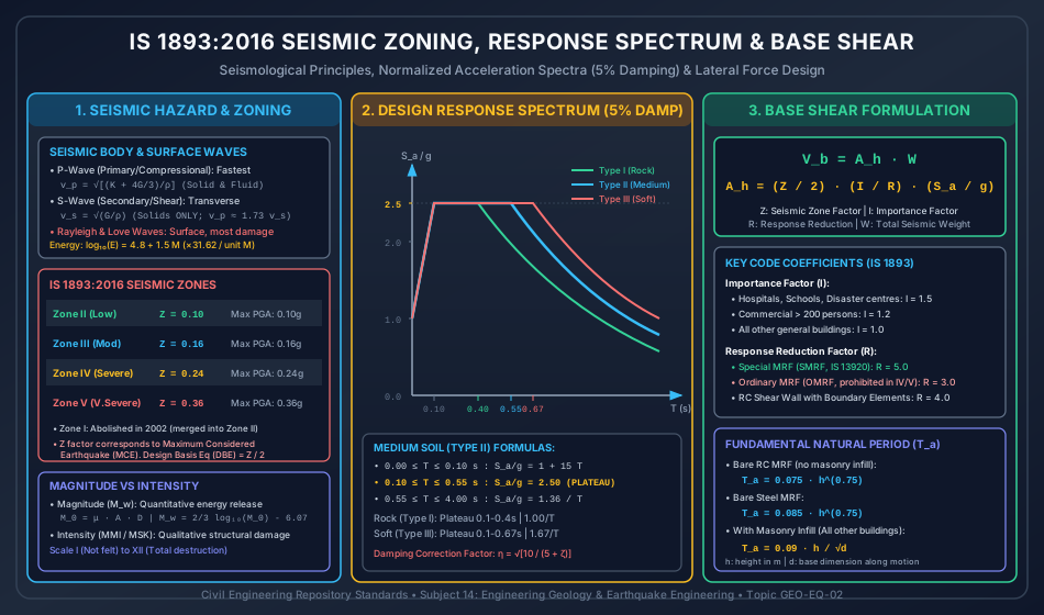
- 5.1 Seismic Hazard, Zoning & Design Response Spectra
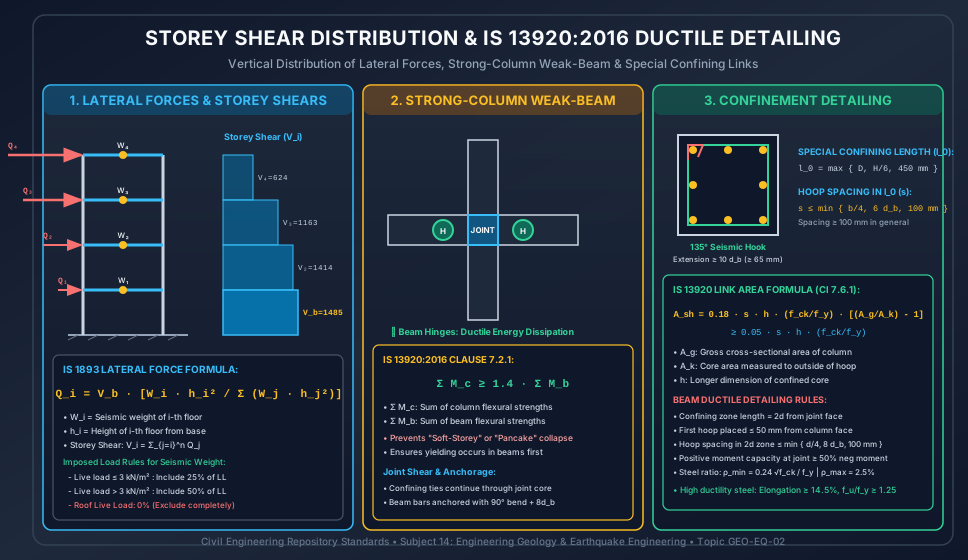
- 5.2 Storey Shear Distribution & IS 13920 Ductile Detailing
- 6. Standard Practice Guidelines & Boundary Conditions
- 6.1 Seismic Weight Calculation Guidelines (IS 1893 Cl 7.3)
- 6.2 Structural Regularity & Irregularity Criteria
- 6.3 Ductile Detailing Rules (IS 13920:2016)
- 7. Critical Failure Modes & Edge Cases
- 7.1 Classic Earthquake Failure Modes in RC Buildings
- 8. Worked Numerical Problems
- Problem 1: Equivalent Static Base Shear & Vertical Storey Shear Distribution (IS 1893:2016)
- Problem 2: SDOF Structural Dynamics (Natural Frequency, Damping Decay, and Resonant Ground Excitation)
- Problem 3: IS 13920:2016 Ductile Confining Reinforcement Design for Columns
- 9. Comparative Exam Analysis
- 10. Common Pitfalls & Traps
- 11. Real-World Civil & Structural Applications
- 12. Comprehensive Summary & Quick Revision Guide
- 13. Practice Problems for Self-Assessment
- 14. References & Standard Texts
1. Executive Summary & Core Definitions
Earthquake Engineering is the branch of civil and structural engineering concerned with designing, analyzing, constructing, and retrofitting structures to withstand tectonic ground motions without catastrophic collapse, minimizing life-safety hazards and economic loss. Modern seismic design operates on the paradigm of ductile capacity design: rather than attempting to resist massive seismic inertia forces elastically (which would require economically prohibitive cross-sections), structures are engineered to undergo controlled, inelastic, ductile deformation while retaining vertical load-carrying capacity.
Core Terminology & Definitions
- Focus (Hypocenter): The actual point of fault rupture initiation within the Earth's crust where seismic strain energy is released.
- Epicenter: The geographical point on the Earth's surface vertically above the focus.
- Focal Depth (): Vertical distance from epicenter to hypocenter (Shallow: ; Intermediate: ; Deep: ). Shallow earthquakes cause the most intense structural destruction.
- Seismic Waves: Stress waves radiating through the earth. Categorized into Body Waves (Compressional Primary -waves and Transverse Shear -waves) and Surface Waves (Rayleigh waves with retrograde elliptical motion and Love waves with transverse horizontal shear).
- Intensity: A qualitative assessment of earthquake shaking severity and resulting structural/environmental damage at a specific geographical location, traditionally quantified using the Modified Mercalli Intensity (MMI) or Medvedev-Sponheuer-Karnik (MSK-64) scales (Grades I to XII).
- Magnitude: A quantitative measurement of the total energy released at the earthquake source. Modern engineering uses the Moment Magnitude (), directly related to the physical seismic moment ().
- Response Spectrum: A graphical plot of the maximum peak response (spectral acceleration , pseudo-velocity , or displacement ) of an ensemble of idealized single-degree-of-freedom (SDOF) damped elastic oscillators subjected to a specific ground motion accelerogram, plotted as a function of the oscillator's natural period () and damping ratio ().
- Design Basis Earthquake (DBE): The ground motion level with a probability of exceedance in 50 years (return period ). Structures must remain functionally repairable under DBE. In IS 1893:2016, DBE acceleration is taken as half of MCE ().
- Maximum Considered Earthquake (MCE): The maximum ground motion expected based on geological fault capabilities, with a probability of exceedance in 50 years (return period ). Structures must not collapse under MCE, though significant structural damage is acceptable. Represented by zone factor .
- Equivalent Static Lateral Force: An idealized set of horizontal static forces whose application at floor levels produces internal shears and moments matching the dynamic envelope of the fundamental vibration mode.
2. Foundational Principles & Governing Axioms
2.1 Engineering Seismology & Wave Propagation Mechanics
When tectonic strain along a fault exceeds the shear strength of the crustal rock, sudden slip occurs according to Reid's Elastic Rebound Theory (1906). The released energy propagates as elastic stress waves governed by continuum elastodynamics:
                          Ground Surface
                                │ Epicenter
                                ▼
                       ┌────────────────┐
                       │                │
                       │   Surface      │ Rayleigh & Love Waves
                       │   Waves        │ (High Amplitude, Slow)
                       │                │
───────────────────────┼────────────────┼───────────────────────
                       │     ▲   ▲      │
                       │    /     \     │
                       │   /       \    │ Body Waves:
                       │  /         \   │ P-Waves (Fast, Compressional)
                       │ /           \  │ S-Waves (Shear, Transverse)
                       │/             \ │
                       * Focus / Hypocenter
                       (Fault Rupture Zone)
- Primary Waves (-Waves):
- Longitudinal, compressional, acoustic dilatational waves. Particle motion is parallel to wave propagation direction.
- Propagate through both solid rock and fluids (liquids and gases).
- Propagation velocity in elastic continuum:
- Secondary Waves (-Waves):
- Transverse, shear, rotational waves. Particle motion is strictly perpendicular to wave propagation direction.
- S-waves require shear stiffness (); therefore, -waves cannot propagate through fluids (water, petroleum, or Earth's liquid outer core).
- Propagation velocity:
- Ratio of wave speeds for typical rock with Poisson's ratio :
- Thus, -waves arrive at seismic recording stations first, followed by the slower, more damaging -waves.
- Surface Waves (Rayleigh & Love Waves):
- Generated by body wave interactions at the stress-free ground surface.
- Love waves: Horizontally polarized shear waves guided within superficial crustal layers; no vertical motion.
- Rayleigh waves: Elliptical retrograde particle motion in the vertical plane parallel to propagation.
- Surface waves decay geometrically as (compared to for spherical body waves), making them the primary agents of structural destruction at distant epicentral ranges.
2.2 SDOF Structural Dynamics & Dynamic Magnification
A single-storey structure or lumped-mass civil system subjected to horizontal ground acceleration is governed by Newton's second law:
        u(t) (Relative Displacement)
         ──►
     ┌─────────┐
     │  Mass   │ ──► Inertia Force: -m · [ü(t) + ü_g(t)]
     │    m    │
     └─────────┘
      │       │
  k   │       │ c (Viscous Damper)
 (Stiffness)  │
      │       │
══════╧═══════╧══════ Ground Motion: ü_g(t)
Dynamic equation of motion:
Dividing across by mass :
Where:
- = Undamped natural circular frequency ()
- = Undamped natural cyclic frequency ()
- = Natural fundamental period ()
- = Critical damping coefficient ()
- = Damping ratio (dimensionless; for reinforced concrete, for welded steel)
- = Damped natural circular frequency
Free Damped Vibration & Logarithmic Decrement
For an underdamped oscillator (), the free vibration response from initial displacement is:
The rate of amplitude decay between two consecutive vibration peaks separated by damped period defines the Logarithmic Decrement ():
Over complete cycles:
3. Step-by-Step Analytical Derivations
3.1 Harmonic Base Excitation & Dynamic Magnification Factor (DMF)
Consider harmonic ground acceleration , where is the forcing frequency. The steady-state relative displacement response is:
Substituting into the differential equation and defining frequency ratio :
Where:
- is the equivalent static deflection under peak ground inertia force .
- is the Dynamic Magnification Factor.
Peak Resonant Response:
At resonance ():
For standard reinforced concrete structures with ( damping):
The dynamic relative displacement and internal bending moments are magnified tenfold compared to the static equivalent load.
3.2 Analytical Derivation of IS 1893:2016 Base Shear Formulation
In modal analysis, the base shear of a multi-storey building in the -th mode is:
where modal participation factor .
For the fundamental mode of a regular multi-storey building, and effective modal mass . IS 1893:2016 establishes the Design Horizontal Seismic Coefficient ():
Derivation of Coefficient Components:
- Factor (Zone Factor): Corresponds to the Maximum Considered Earthquake (MCE) peak ground acceleration (PGA).
- Divisor (Design Basis Earthquake): Reduces MCE to DBE (). The code designs structural components for DBE elastic limits, relying on ductility to absorb the remaining demand during MCE.
- Factor (Importance Factor): Scales up safety for critical facilities (hospitals, schools, communication towers) to ensure operational continuity post-disaster.
- Divisor (Response Reduction Factor): Accounts for structural ductility (), overstrength (), and material damping redundancy: For ductile SMRF (), forces are reduced to of elastic demand; for brittle OMRF (), forces are reduced to .
- Spectral Ratio : Normalized elastic response acceleration derived from site soil class and building period .
Total Design Seismic Base Shear ():
3.3 Derivation of Vertical Storey Shear Distribution
In dynamic mode superposition, the lateral inertial force at floor in mode 1 is:
For a multi-storey building with uniform floor mass, the fundamental mode shape can be approximated as:
- Linear () for low-rise shear buildings.
- Parabolic () for mid-to-high rise buildings dominated by flexural frame-shear wall deformation.
IS 1893:2016 adopts the quadratic distribution to safely envelope higher mode effects (whiplash action at upper storeys):
Integrating from the roof downwards yields the Storey Shear () at floor level :
3.4 Ductile Confining Reinforcement Derivation (IS 13920:2016)
When an RC column experiences large cyclic lateral drifts during an earthquake, the unconfined concrete cover spalls away. To prevent catastrophic explosive core crushing, transverse rectilinear hoops must provide passive lateral confining pressure .
From Richart's triaxial confinement model:
For a rectangular column core with confinement width and hoop vertical spacing , the tensile bursting force resisted by hoop legs of area at yield stress is:
To maintain the column axial capacity after cover spalling ():
Incorporating safety margins for cyclic degradation and cross-tie efficiency, IS 13920:2016 (Clause 7.6.1) specifies:
4. Key Formulas & Summary Tables
4.1 Governing Seismic & Dynamics Formulas
| Parameter / Relation | Governing Equation | Physical Meaning / Code Reference |
|---|---|---|
| Natural Period (SDOF) | Fundamental elastic period of vibration () | |
| Damped Frequency | Oscillation frequency with viscous damping () | |
| Logarithmic Decrement | Rate of cyclic amplitude decay over cycles | |
| Dynamic Magnification | Amplification factor at resonance () | |
| Horizontal Coefficient | Design horizontal seismic acceleration coefficient (IS 1893) | |
| Base Shear | Total lateral seismic base shear force () | |
| Floor Lateral Force | Parabolic lateral force at floor level (IS 1893 Cl 7.6.3) | |
| Storey Shear | Cumulative horizontal shear at storey () | |
| Period (Bare RC MRF) | Height in meters (IS 1893 Cl 7.6.2a) | |
| Period (Infilled MRF) | = base dimension in direction of motion (Cl 7.6.2b) | |
| Strong Column Rule | Strong-column weak-beam condition (IS 13920 Cl 7.2.1) | |
| Confining Link Area | Rectangular hoop area in special confining zone (IS 13920) |
4.2 IS 1893:2016 Code Parameter Summary Tables
A. Seismic Zone Factors ()
| Seismic Zone | Intensity Level | Zone Factor () | Design Basis Peak Acceleration () |
|---|---|---|---|
| Zone II | Low | ||
| Zone III | Moderate | ||
| Zone IV | Severe | ||
| Zone V | Very Severe |
B. Importance Factors ()
| Structure Occupancy / Functional Importance | Importance Factor () |
|---|---|
| Critical lifeline facilities: Hospitals, disaster management centres, fire stations, telecommunications, schools | |
| Commercial, community & residential buildings designed for occupancy persons | |
| All other regular commercial, industrial, and residential structures |
C. Response Reduction Factors ()
| Lateral Load Resisting Structural System | Factor () | Ductility / Code Enforcement |
|---|---|---|
| Special Moment Resisting Frame (SMRF) | Mandates full ductile detailing per IS 13920:2016 | |
| Ordinary Moment Resisting Frame (OMRF) | Prohibited in Zones IV & V; permitted only in II & III | |
| RC Structural Shear Wall (Ductile) | Requires special boundary elements per IS 13920 | |
| Steel Frame with Concentric Bracings (SCBF) | Complies with IS 800:2007 Section 12 |
5. Visual Architectural Diagrams
5.1 Seismic Hazard, Zoning & Design Response Spectra
5.2 Storey Shear Distribution & IS 13920 Ductile Detailing
6. Standard Practice Guidelines & Boundary Conditions
6.1 Seismic Weight Calculation Guidelines (IS 1893 Cl 7.3)
The total seismic weight () comprises:
- Dead Load (): of self-weight of all slabs, beams, columns, walls, finishes, and permanent partitions.
- Imposed / Live Load ():
- For floors with design live load : Include of design LL.
- For floors with design live load : Include of design LL.
- For roof level: of live load (roof live load is completely excluded; only snow load per IS 875 Part 4 is evaluated if applicable).
6.2 Structural Regularity & Irregularity Criteria
IS 1893:2016 classifies structures into Regular and Irregular. Dynamic analysis (Response Spectrum Method or Time History Method) is mandatory if:
- Building height in Zones IV and V.
- Building height in Zones II and III.
- Plan irregularities exist:
- Torsional Irregularity: Maximum drift .
- Re-entrant Corners: Projection dimensions plan dimension.
- Diaphragm Discontinuity: Openings floor area.
- Vertical irregularities exist:
- Soft Storey (Stiffness Irregularity): Lateral stiffness of storey above, or of average stiffness of three storeys above.
- Weak Storey (Strength Irregularity): Lateral shear strength of storey above.
6.3 Ductile Detailing Rules (IS 13920:2016)
- Beams (Flexural Members):
- Minimum clear cover = (or bar diameter).
- ; .
- Positive moment resistance at joint face must be of negative moment resistance.
- Confining links over zone from column faces: spacing . First link placed within of column face.
- Columns (Frame Members Subject to Axial & Bending):
- Minimum column dimension: (or of largest longitudinal beam bar).
- Longitudinal steel: .
- Special confining zone length .
- Confining link spacing .
- All links must terminate in seismic hooks with extension (minimum ) anchored into the concrete core.
7. Critical Failure Modes & Edge Cases
7.1 Classic Earthquake Failure Modes in RC Buildings
- Soft Storey / Stilt Floor Failure (Bhuj Earthquake, 2001):
- Ground floor left open without masonry infill walls for parking ("stilt floor"), while upper storeys have brick infills.
- Failure Mechanism: The upper infilled storeys act as quasi-rigid blocks, concentrating all inelastic lateral drift and shear deformation in the flexible, unbraced ground floor columns. The columns form plastic hinges at top and bottom, leading to catastrophic pancake collapse.
- IS 1893:2016 Remedy: Columns and beams of soft storeys must be designed for times the storey shears calculated from regular bare-frame analysis, or ductile RC shear walls must be introduced.
- Short Column Effect (Captive Columns):
- Partial-height masonry infill walls (e.g., ribbon windows for ventilation) confine the middle portion of an RC column, drastically reducing its clear unsupported height from to .
- Failure Mechanism: Lateral stiffness increases inversely as cube of height (), attracting massive shear forces (). The column fails in brittle shear along diagonal tension cracks prior to flexural yielding.
- P-Delta Collapse under Extreme Cyclic Drift:
- Large lateral storey drift () combined with high vertical gravity loads () generates secondary overturn moments ().
- If lateral stiffness degrades due to cyclic concrete cracking, the negative geometric stiffness overcomes elastic stiffness, causing complete collapse.
- Torsional Twisting of Asymmetric Buildings:
- Center of Mass () does not coincide with Center of Rigidity (), creating an eccentricity . Lateral seismic force generates a twisting torque , subjecting perimeter corner columns to extreme compounded shear and drift.
8. Worked Numerical Problems
Problem 1: Equivalent Static Base Shear & Vertical Storey Shear Distribution (IS 1893:2016)
Statement:
A 4-storey reinforced concrete hospital building with Special Moment Resisting Frames (SMRF) is to be constructed in Seismic Zone V on medium soil (Type II).
The building features:
- Plan dimensions: (along motion), .
- Storey heights: Ground floor ; First floor ; Second floor ; Roof from the ground base.
- Seismic Weights: Floors 1, 2, and 3: each; Roof level: .
- The building has brick masonry infill walls in all storeys.
Calculate:
- The approximate fundamental natural period of the building ().
- The design horizontal seismic coefficient ().
- The total design seismic base shear ().
- The design lateral force () and cumulative storey shear () at each floor level.
Step-by-Step Analytical Solution
Part 1: Fundamental Natural Period () For a building with masonry infill walls, IS 1893:2016 Clause 7.6.2(b) applies:
Where total height , base dimension along motion :
Part 2: Design Horizontal Seismic Acceleration Coefficient () From IS 1893:2016:
- Zone V Zone factor .
- Hospital building (Critical lifeline facility) Importance factor .
- SMRF structural system Response reduction factor .
- For Medium Soil (Type II) at , which falls in the range :
Substituting into the horizontal seismic coefficient formula:
Part 3: Total Design Seismic Base Shear () Total seismic weight of building:
Part 4: Vertical Distribution of Base Shear () and Storey Shears () Using the parabolic distribution:
Let us compute for each floor:
- Floor 1:
- Floor 2:
- Floor 3:
- Floor 4 (Roof):
Sum of :
Now compute and cumulative :
-
Roof (Floor 4):
-
Floor 3:
-
Floor 2:
-
Floor 1 (Ground Floor):
Problem 2: SDOF Structural Dynamics (Natural Frequency, Damping Decay, and Resonant Ground Excitation)
Statement:
An elevated municipal water tank has a full lumped mass supported by an empty cylindrical reinforced concrete staging shaft. Field vibration testing establishes:
- Total lateral staging stiffness .
- Structural viscous damping ratio ().
Determine:
- The undamped circular frequency (), cyclic frequency (), and natural period ().
- The critical damping coefficient () and actual damping coefficient ().
- The damped natural circular frequency () and logarithmic decrement ().
- The percentage amplitude reduction of free vibration after 3 complete cycles.
- If the base of the tower is subjected to harmonic earthquake ground acceleration with amplitude at resonance (), determine the peak steady-state relative displacement ().
Step-by-Step Analytical Solution
Part 1: Dynamic Frequency & Period
Part 2: Damping Coefficients
Part 3: Damped Frequency & Logarithmic Decrement
Part 4: Amplitude Decay after 3 Cycles
Part 5: Resonant Steady-State Displacement Equivalent static deflection under peak ground inertia force:
Dynamic Magnification Factor at resonance ():
Peak steady-state relative displacement:
Problem 3: IS 13920:2016 Ductile Confining Reinforcement Design for Columns
Statement:
An interior ground-floor column of a 6-storey commercial building in Seismic Zone IV has:
- Column cross-section: .
- Clear column storey height: .
- Concrete grade M30 (); Transverse and longitudinal steel Fe 500 ().
- Main longitudinal bars: 8 bars of diameter ().
- Clear cover to transverse hoops: .
Design the special confining reinforcement per IS 13920:2016:
- Determine the special confining zone length () from the beam-column joint face.
- Determine the maximum allowable spacing () of hoops within .
- Calculate the required total cross-sectional area of rectangular confining hoop legs () and select a suitable link arrangement.
Step-by-Step Analytical Solution
Part 1: Special Confining Length () Per IS 13920:2016 Clause 7.6.1(a), the special confining reinforcement must extend to length from each joint face:
- Column larger dimension
- One-sixth clear height:
- Code minimum:
Adopt special confining length at both top and bottom of the column.
Part 2: Maximum Hoop Spacing within () Per IS 13920:2016 Clause 7.6.1(b), hoop spacing within shall satisfy:
- One-fourth minimum column dimension:
- Six times smallest longitudinal bar:
- Code limit:
Adopt hoop spacing center-to-center.
Part 3: Confining Hoop Cross-Sectional Area () Core dimensions measured to outside of peripheral hoop:
Applying IS 13920:2016 Clause 7.6.1(c):
Minimum check:
Rebar Detailing Selection: Providing an outer rectangular hoop plus two cross-ties across the core gives 4 legs resisting bursting along each principal axis: Using diameter links ():
Detaiing Specification: Provide 4-legged links @ c/c over at both column ends, with seismic hooks having straight extensions.
9. Comparative Exam Analysis
| Parameter / Feature | GATE CE | UPSC ESE (Paper 1 & GS) | SSC JE & State AE | RRB JE |
|---|---|---|---|---|
| Typical Question Formats | Numerical: Base shear , period , SDOF resonance, distribution | Derivations & Code checks: IS 1893 seismic zoning, IS 13920 ductile rebar | Objective / MCQs: Zone factors (), Importance factor (), hook rule | Direct MCQs: Seismic zones of India, P vs S waves, epicenter vs focus |
| Primary Focus Areas | Equivalent static method, SDOF natural frequency & DMF, response spectra | Strong-column weak-beam principle, soft storey failure, confining zone | Values of for Zone II-V, Live load percentages for seismic weight | Body waves vs surface waves, Richter magnitude vs Mercalli intensity |
| Scoring Traps | Confusing DBE () with MCE (); including roof live load | Forgetting multiplier in ; link spacing | Using Zone I (abolished!); using for SMRF instead of | Claiming S-waves travel through liquids; confusing throw and heave |
10. Common Pitfalls & Traps
- Zone Factor vs Design Acceleration:
- Trap: Multiplying seismic weight by .
- Correction: IS 1893 explicitly divides by 2 () because corresponds to MCE, while structures are proportioned for DBE limits.
- Roof Live Load in Seismic Weight:
- Trap: Including or of roof live load in .
- Correction: IS 1893 Clause 7.3.2 strictly specifies of roof live load.
- Response Reduction Factor Misassignment:
- Trap: Using (SMRF) without providing IS 13920 ductile detailing.
- Correction: If a building is not detailed per IS 13920, it cannot claim . Furthermore, OMRF () is prohibited in Zones IV and V.
- Hook Detailing in Seismic Stirrups:
- Trap: Specifying hooks for beam stirrups or column ties.
- Correction: Under cyclic earthquake reversal, concrete cover spalls and hooks untie spontaneously. IS 13920 mandates seismic hooks with extension.
11. Real-World Civil & Structural Applications
- Base Isolation & Energy Dissipation Dampers:
- Lead-rubber bearings (LRB) and friction pendulum systems shift the structural fundamental period from to , moving the building off the peak spectral acceleration plateau () down into the low-force descending branch ().
- Post-Earthquake Retrofitting (Bhuj & Sikkim):
- Jacketing RC columns with micro-concrete and high-strength confinement ties, adding external steel bracings, and introducing shear walls to eliminate soft-storey vulnerabilities.
- Seismic Instrumentation of Mega-Structures (Atal Bridge, Chenab Bridge):
- Triaxial accelerometers and tilt sensors installed at foundations, piers, and deck levels record structural dynamic response to verify real-time damping and modal frequencies against design models.
12. Comprehensive Summary & Quick Revision Guide
- Seismic Waves: -waves (fastest, compressional, solid & liquid) -waves (transverse shear, solids only, ) Surface waves (Rayleigh/Love, most destructive).
- Seismic Zones: II (), III (), IV (), V (). Zone I is abolished.
- Base Shear: , where .
- Vertical Lateral Force: . Storey shear .
- Period Formulas: Bare RC: ; Infilled RC: .
- Imposed Load for Seismic Weight: LL ; LL ; Roof LL .
- Strong Column Weak Beam: .
- Column Confinement Length: .
- Hoop Spacing in : . Must have hooks with extension.
- Confining Link Area: .
13. Practice Problems for Self-Assessment
- Base Shear Practice: A 5-storey regular SMRF office building () located in Seismic Zone IV on rock/hard soil (Type I) has a total seismic weight of . The calculated natural period is (falls on plateau ). Calculate the design base shear.
(Answer: ) - SDOF Resonance Practice: An industrial chimney of mass has lateral stiffness and damping . Find the natural frequency and resonant dynamic magnification factor.
(Answer: ; ) - Column Confinement Practice: An RC column of dimension has clear height and longitudinal bar diameter . Find the special confining length and maximum allowable tie spacing .
(Answer: ; )
14. References & Standard Texts
- IS 1893 (Part 1): 2016, Criteria for Earthquake Resistant Design of Structures - General Provisions and Buildings, Bureau of Indian Standards, New Delhi.
- IS 13920: 2016, Ductile Design and Detailing of Reinforced Concrete Structures Subjected to Seismic Forces - Code of Practice, Bureau of Indian Standards, New Delhi.
- IS 4326: 2013, Earthquake Resistant Design and Construction of Buildings - Code of Practice, Bureau of Indian Standards, New Delhi.
- Anil K. Chopra, Dynamics of Structures: Theory and Applications to Earthquake Engineering, 5th Edition, Pearson Education, 2020.
- Pankaj Agarwal and Manish Shrikhande, Earthquake Resistant Design of Structures, PHI Learning, 2011.
- C.V.R. Murty, IITK-BMTPC Earthquake Tips: Learning Earthquake Design and Construction, Building Materials & Technology Promotion Council, New Delhi.