Engineering Geology: Rock Taxonomy, Mineralogy, Geological Structures & Infrastructure Site Selection
In this chapter (1 topics)
On this page
- 1. Executive Summary & Core Definitions
- Core Terminology & Definitions
- 2. Foundational Principles & Governing Axioms
- 2.1 The Rock Cycle & Petrogenetic Classification
- 2.2 Physical Mineralogy & Diagnostic Properties
- 3. Step-by-Step Analytical Derivations
- 3.1 Geometric Derivation of True Dip vs Apparent Dip
- 3.2 Fault Kinematics & Displacement Decomposition
- 3.3 Deere's Rock Quality Designation (RQD) Formulation
- 4. Key Formulas & Summary Tables
- 4.1 Summary of Governing Mathematical Formulas
- 4.2 Engineering Rock Mass Quality Classifications
- 5. Visual Architectural Diagrams
- 5.1 Rock Taxonomy, Strike-Dip Geometry & Fault Mechanics
- 5.2 Dam & Tunnel Site Selection Criteria & RQD System
- 6. Standard Practice Guidelines & Boundary Conditions
- 6.1 Dam Site Geological Assessment
- 6.2 Tunnel Alignment Criteria
- 7. Critical Failure Modes & Edge Cases
- 7.1 Classic Geological Infrastructure Disasters
- 8. Worked Numerical Problems
- Problem 1: True Dip Calculation from Strike Azimuth & Apparent Dip
- Problem 2: Fault Displacement Decomposition (Throw, Heave, and Net Oblique Slip)
- Problem 3: Rock Quality Designation (RQD) and Bieniawski RMR Foundation Rating
- 9. Comparative Exam Analysis
- 10. Common Pitfalls & Traps
- 11. Real-World Civil & Structural Applications
- 12. Comprehensive Summary & Quick Revision Guide
- 13. Practice Problems for Self-Assessment
- 14. References & Standard Texts
1. Executive Summary & Core Definitions
Engineering Geology is the discipline that bridges geological science and civil engineering practice. It investigates the earth's materials—minerals, rocks, sediments, and groundwater—and geological structures to ensure that geological factors affecting the location, design, construction, operation, and maintenance of engineering works are recognized, quantified, and accommodated.
Core Terminology & Definitions
- Mineral: A naturally occurring, inorganic, homogeneous solid substance possessing a definite chemical composition and an ordered internal atomic lattice structure. Over 4,000 minerals exist, but engineering geology focuses primarily on rock-forming minerals (silicates, carbonates, sulfates, oxides).
- Rock: An aggregate of one or more minerals, or mineraloids, forming an essential component of the Earth's crust. Classified genetically into Igneous, Sedimentary, and Metamorphic.
- Strike: The compass direction (azimuth or quadrant bearing) of a horizontal line formed by the intersection of an inclined geological plane (bedding, joint, fault, foliation) with a horizontal reference plane.
- Dip: The angle of maximum inclination of a geological plane measured downward from the horizontal plane (). The Dip Direction is always strictly perpendicular to the strike azimuth ( clockwise or counter-clockwise depending on dip slope).
- Apparent Dip: The angle of inclination of a plane measured in any vertical cross-section that is not perpendicular to the strike line (). The apparent dip is always strictly less than the true dip ().
- Fold: A wavy undulation or curvature produced in layered or stratified rocks due to compressive tectonic stresses over geological time.
- Fault: A fracture or fracture zone along which there has been observable relative displacement of the adjacent rock blocks parallel to the fracture plane.
- Joint: A natural fracture or parting in rock along which there has been little or no transverse shear displacement (distinguishing it from a fault).
- Rock Quality Designation (RQD): A standardized quantitative index (Deere, 1964) of core recovery quality, defined as the percentage of borehole drill run consisting of sound intact cylindrical core pieces () in length.
- Rock Mass Rating (RMR): A geomechanical classification system (Bieniawski, 1973/1989) combining intact rock strength, RQD, discontinuity spacing, joint surface conditions, and groundwater to evaluate rock mass competence and stand-up time.
2. Foundational Principles & Governing Axioms
2.1 The Rock Cycle & Petrogenetic Classification
Rocks evolve continuously through igneous, sedimentary, and metamorphic transformations:
[Magma / Lava]
      │ (Cooling & Crystallization)
      ▼
[IGNEOUS ROCKS] ──(Weathering, Erosion, Deposition)──► [Sediments]
      │                                                     │
  (Heat &                                             (Lithification /
  Pressure)                                            Diagenesis)
      │                                                     │
      ▼                                                     ▼
[METAMORPHIC ROCKS] ◄──(Heat, Stress, Hydrothermal)── [SEDIMENTARY ROCKS]
      │
  (Deep Subduction & Melting)
      ▼
   [Magma]
A. Igneous Rocks
Formed by the solidification of molten rock material (magma within crust, lava at surface):
- Plutonic (Intrusive, Deep-seated): Slow cooling insulated deep beneath surface fully crystallized, coarse-grained phaneritic texture.
- Granite: Felsic rock rich in quartz (), potassium feldspar (orthoclase), plagioclase, and mica (biotite/muscovite). High unconfined compressive strength (), high density (), excellent dam/bridge foundation when unweathered.
- Gabbro: Mafic plutonic rock consisting of plagioclase and pyroxene (augite). Dense, tough, dark-colored.
- Diorite: Intermediate plutonic rock ("salt and pepper" appearance) composed of plagioclase and hornblende.
- Peridotite: Ultramafic rock rich in olivine and pyroxene.
- Hypabyssal (Sub-volcanic, Medium Depth): Formed in dykes, sills, and laccoliths under intermediate cooling rates medium-grained to porphyritic (large phenocrysts in fine groundmass).
- Dolerite (Diabase): Chemically equivalent to basalt/gabbro; exhibits interlocking ophitic texture; exceptionally tough and ideal for railway ballast and concrete aggregate.
- Volcanic (Extrusive): Rapid quenching of lava at surface or underwater fine-grained aphanitic, glassy (obsidian), or vesicular/scoriaceous texture (pumice).
- Basalt: Most widespread volcanic rock on Earth (e.g., Deccan Traps in India). Dominantly plagioclase and pyroxene. Often exhibits columnar jointing, vesicular zones, and amygdaloidal cavities filled with zeolites/calcite. Competent when massive, but inter-trappean red bole / ash beds represent severe sliding failure planes in dam foundations.
- Rhyolite: Extrusive equivalent of granite; light-colored, viscous lava origin.
B. Sedimentary Rocks
Formed by accumulation, compaction, and cementation of mineral particles (clastic) or chemical precipitation:
- Mechanical / Clastic Deposits:
- Rudaceous (Coarse ): Conglomerate (rounded gravels/pebbles cemented in matrix) and Breccia (angular rock fragments indicating minimal transport).
- Arenaceous (Medium ): Sandstone (predominantly quartz grains cemented by silica, calcite, iron oxide, or clay). Siliceous sandstone has highest strength; clayey matrix sandstone slakes upon water saturation.
- Argillaceous (Fine ): Siltstone, Mudstone, and Shale. Shale exhibits fissility (delamination along micro-bedding planes); low shear strength; swells and disintegrates under wetting-drying cycles.
- Chemical Precipitates:
- Limestone: Calcium carbonate (, calcite). Susceptible to chemical dissolution by carbonic acid (), forming sinkholes, caverns, and karst topography. High engineering hazard for dam reservoirs (uncontrollable water loss).
- Dolomite: Calcium magnesium carbonate (); less soluble and denser than limestone.
- Evaporites: Gypsum (), Anhydrite (), Rock Salt (). Anhydrite swells by upon hydration to gypsum, generating immense swelling pressure in tunnels.
- Organic / Biogenic Deposits: Coal, Peat, Lignite, Chalk, Diatomite. Highly compressible, low bearing capacity.
C. Metamorphic Rocks
Formed by solid-state mineralogical and structural reconstitution of pre-existing rocks under extreme temperatures, confining pressures, directional tectonic shear, and hydrothermal fluid action:
- Foliated Rocks (Progressive Metamorphic Grade):
- Slate: Low-grade metamorphism of shale; excellent slaty cleavage; used for roofing tiles.
- Phyllite: Intermediate grade; silky sheen on cleavage surfaces due to micro-crystalline sericite/chlorite.
- Schist: Medium-to-high grade; coarse parallel alignment of platy/flaky minerals (mica schist, chlorite schist, talc schist). Schistosity represents planes of extreme weakness and anisotropic sliding.
- Gneiss: High-grade metamorphism; alternating light-colored felsic bands (quartz, feldspar) and dark mafic bands (biotite, hornblende); massive, durable foundation rock.
- Non-Foliated (Granoblastic) Rocks:
- Quartzite: Metamorphism of quartz sandstone; recrystallized interlocking quartz crystals. Hardest common rock (Mohs 7), chemically inert, extremely abrasive to tunnel boring machines (TBMs), high compressive strength ().
- Marble: Metamorphism of limestone/dolomite; recrystallized calcite/dolomite crystals. Susceptible to dissolution and acid rain degradation.
2.2 Physical Mineralogy & Diagnostic Properties
The physical properties of minerals govern rock behavior:
- Hardness (Mohs Scale): A relative scale of scratch resistance based on 10 standard minerals:
- : Talc (softest, soapy feel)
- : Gypsum (scratched by fingernail)
- : Calcite (scratched by copper coin )
- : Fluorite (cleaves easily in octahedra)
- : Apatite (scratched by pocket knife/glass )
- : Orthoclase Feldspar (scratches glass, scratched by streak plate )
- : Quartz (scratches streak plate; lacks cleavage; conchoidal fracture)
- : Topaz
- : Corundum
- : Diamond (hardest known natural substance)
- Standard Field Testing Mnemonic: "The Girls Can Flirt And Other Queer Things Can Do"
- Cleavage: Tendency of a crystalline mineral to split along definitive planes of weak atomic bonding:
- Basal / Perfect in 1 direction: Mica (Biotite, Muscovite).
- Prismatic in 2 directions: Feldspar (), Amphibole (), Pyroxene ().
- Rhombohedral in 3 directions: Calcite ().
- Cubic in 3 directions: Halite, Galena ().
- Fracture: Texture of the broken surface when mineral breaks across cleavage:
- Conchoidal (curved shell-like ridges): Quartz, Obsidian.
- Hackly (sharp, jagged edges): Native copper.
- Uneven / Splintery: Asbestos, kyanite.
- Streak: Color of the mineral's finely powdered residue obtained by rubbing against an unglazed porcelain streak plate (hardness ):
- Hematite (): Steel gray to black mineral, but cherry-red / reddish-brown streak.
- Pyrite ( - "Fool's Gold"): Brass-yellow mineral, but greenish-black streak.
- Magnetite (): Black mineral, black streak, magnetic.
3. Step-by-Step Analytical Derivations
3.1 Geometric Derivation of True Dip vs Apparent Dip
Consider an inclined geological bedding plane dipping at true angle along true dip azimuth . We seek the apparent dip angle measured along an arbitrary azimuth direction inclined at angle to the true dip direction.
       Plan View (Horizontal Datum Plane)

              Strike Line (Horizontal)
       A ─────────────────────────────── B
         \              |              /
          \             |             /
           \            |            /
            \           |           /
             \          | d         /
            s \         |          /
               \        |         /
                \   β   |        /
                 \      |       /
                  \     |      /
                   \    |     /
                    \   |    /
                     \  |   /
                      \ |  /
                       \│ /
                        C
Let:
- Point be on the strike line at datum elevation .
- Along the true dip direction (), the bed drops by vertical depth over horizontal distance .
- Along the apparent dip direction (), the bed drops by the same vertical depth over horizontal distance .
From the right-angled triangle in the horizontal plane:
From the vertical cross-sections:
-
In the true dip vertical plane:
-
In the apparent dip vertical plane:
Equating the two expressions for vertical drop :
Dividing both sides by :
Inversion Formula: True Dip from Two Apparent Dips
If two apparent dips and are measured along directions making angles and with the unknown true dip direction, and the angle between the two apparent directions is :
3.2 Fault Kinematics & Displacement Decomposition
Consider an inclined planar fault dipping at angle from the horizontal. A marker horizon (bedding contact or mineral vein) is displaced along the fault plane by net slip vector .
                 Hanging Wall (moves down)
                        │
                        ▼
       Footwall        /══════════════ Fault Plane
       ┌──────────────/
       │             /│
       │            / │
       │           /  │ Throw (T = S_dip · sin δ)
       │          /   │
       │         /────┘
       │        / Heave (H = S_dip · cos δ)
       │       /
       │  δ   /
───────┴─────/────────────────────── Horizontal Datum
-
Hade Angle (): The angle between the inclined fault plane and the vertical plane:
-
Dip-Slip Component (): The component of displacement parallel to the dip line of the fault plane.
- Throw (): The vertical component of dip displacement:
- Heave (): The horizontal component of dip displacement measured in the direction of dip:
Relating Throw and Heave directly to Hade and Dip:
-
Oblique Slip & Rake (Pitch): When movement includes both dip-slip () and strike-slip ():
3.3 Deere's Rock Quality Designation (RQD) Formulation
Introduced by D.U. Deere in 1964, RQD quantifies borehole core recovery quality using a standard diamond core drilling barrel ( size, core diameter, or double-tube wireline core barrel):
Where:
- = Length of intact, sound, cylindrical rock core pieces along the core centerline.
- Core breaks caused mechanically by the drilling or handling process are fitted together and counted as continuous sound pieces.
- Highly weathered, altered, or plastic zones are excluded even if pieces exceed .
Palmström's Volumetric Joint Count () Correlation
When drill cores are unavailable (e.g., surface exposures, adits, tunnel faces), RQD is estimated from the volumetric joint count (number of joints intersecting a block):
where is the average spacing of the -th joint set in meters.
- If
- If
4. Key Formulas & Summary Tables
4.1 Summary of Governing Mathematical Formulas
| Parameter / Relation | Governing Mathematical Equation | Physical Meaning / Units |
|---|---|---|
| Apparent Dip | : apparent dip; : true dip; : angle between azimuths | |
| Fault Throw | Vertical separation of beds across fault plane () | |
| Fault Heave | Horizontal separation in dip direction () | |
| Hade Angle | Complement of dip angle measured from vertical () | |
| Net Fault Slip | Total relative 3D displacement vector magnitude () | |
| RQD Index | Percent of intact sound core pieces () | |
| Palmström RQD | ; empirical correlation | |
| Bieniawski RMR | Sum of 5 basic ratings + orientation adjustment (0 to 100) |
4.2 Engineering Rock Mass Quality Classifications
A. Deere's RQD Engineering Description
| RQD Range (%) | Rock Mass Quality Description | General Engineering Behavior |
|---|---|---|
| Very Poor | Heavily shattered, crushed, requiring full immediate support / steel ribs | |
| Poor | Closely jointed, frequent block fallouts, shotcrete + rock bolts required | |
| Fair | Moderately jointed, stable under light rock bolting | |
| Good | Massive with widely spaced joints, minimal support required | |
| Excellent | Intact, massive rock, unsupported spans feasible |
B. Bieniawski's Rock Mass Rating (RMR) System
| Parameter | Range of Values & Rating Points |
|---|---|
| 1. Intact Rock Strength (UCS) | (15 pts) (12 pts) (7 pts) (4 pts) (0-2 pts) |
| 2. RQD | (20 pts) (17 pts) (13 pts) (8 pts) (3 pts) |
| 3. Joint Spacing | (20 pts) (15 pts) (10 pts) (8 pts) (5 pts) |
| 4. Joint Condition | Very rough, unweathered, tight (30 pts) Slightly rough, aperture (25 pts) Gouge (10 pts) Soft gouge (0 pts) |
| 5. Groundwater | Completely dry (15 pts) Damp (10 pts) Wet (7 pts) Dripping (4 pts) Flowing under pressure (0 pts) |
| Adjustment () | Tunnels: 0 (Very fav) to (Very unfav) | Dams: 0 (Very fav) to (Very unfav) | Slopes: 0 to |
| RMR Class | Total Rating | Classification | Cohesion () | Friction Angle () | Safe Bearing Capacity |
|---|---|---|---|---|---|
| Class I | Very Good Rock | ||||
| Class II | Good Rock | ||||
| Class III | Fair Rock | ||||
| Class IV | Poor Rock | ||||
| Class V | Very Poor Rock |
5. Visual Architectural Diagrams
5.1 Rock Taxonomy, Strike-Dip Geometry & Fault Mechanics
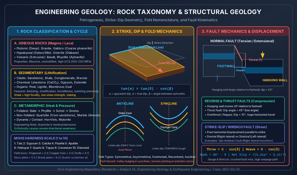
5.2 Dam & Tunnel Site Selection Criteria & RQD System
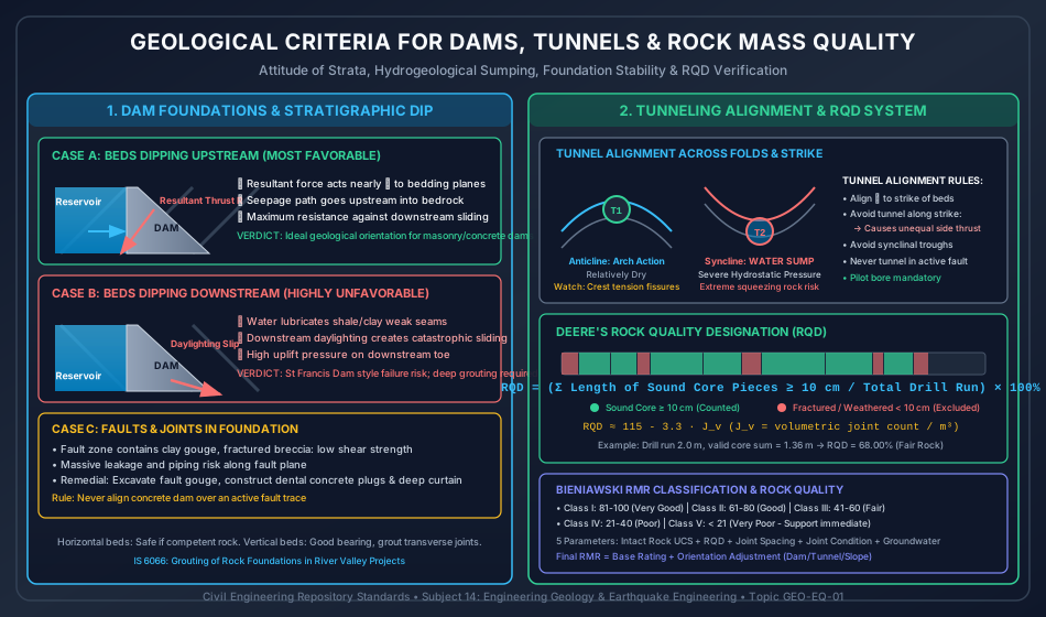
6. Standard Practice Guidelines & Boundary Conditions
6.1 Dam Site Geological Assessment
-
Bedding Dip Criteria for Concrete Gravity Dams:
- Upstream Dipping Strata (Angle ): Optimal / Most Favorable. The resultant vector of reservoir hydrostatic thrust and self-weight of the dam cuts the bedding planes at approximately . Seepage path is directed upstream, minimizing downstream pore pressure and foundation uplift.
- Downstream Dipping Strata (Angle ): Extremely Hazardous. The resultant load drives foundation sliding along bedding planes. If bedding daylights downstream in the river gorge, catastrophic daylighting shear failure can occur. Requires extensive shear keys, rock anchors, and downstream drainage galleries.
- Horizontal Strata: Moderate to favorable, provided rock layers are competent (e.g., thick sandstone, basalt). Weak shale or clay interbeds can trigger sliding on horizontal planes under high reservoir thrust.
- Vertical Strata: High bearing capacity across bed heads; prevents sliding along bedding; but transverse jointing across the river canyon can allow high reservoir water leakage unless sealed by deep grout curtains.
-
Geological Faults in Dam Foundations:
- Active faults (Holocene displacement within last 11,000 years): Absolute site disqualification. No rigid dam can tolerate differential tectonic shear.
- Inactive / Ancient faults: If an ancient fault crosses the dam axis, the fault zone must be excavated to sound rock, backfilled with dental concrete (dental treatment), and reinforced with multi-row curtain grouting (IS 6066:2020).
6.2 Tunnel Alignment Criteria
- Alignment with Respect to Strike:
- Perpendicular to Strike (): Best Alignment. Tunnel cuts across strata in the shortest distance; rock pressure is symmetrically distributed on both sidewalls; roof arching action is maximized.
- Parallel to Strike (): Unfavorable. If beds dip into the tunnel, one sidewall experiences intense lateral crushing thrust while the opposite wall experiences decompression or daylighting block slide.
- Alignment through Fold Structures:
- Anticlines: Favorable due to natural arch action and compressive rock mass locking. However, the anticlinal crest exhibits tension fissures where wedge fallouts and block detaching occur; tunnel should be placed slightly off the crest.
- Synclines: Worst Possible Alignment. Synclines act as regional geological aquifers and groundwater sumps. Perched water, intense artesian hydrostatic head, and severe squeezing rock conditions are encountered in the synclinal core.
- Overburden & In-situ Stress States:
- High overburden (): Horizontal tectonic stress can trigger catastrophic rock bursts (explosive spalling of brittle rock) in granites and quartzites, or plastic squeezing in shales and phyllites.
7. Critical Failure Modes & Edge Cases
7.1 Classic Geological Infrastructure Disasters
- St. Francis Dam Disaster (USA, 1928):
- Geological Cause: Concrete gravity dam built across an ancient fault contact separating Pelona Schist on the east abutment and Sespe red conglomerate on the west.
- Failure Mechanism: The conglomerate contained gypsum and clay matrix that dissolved and slaked rapidly upon reservoir filling. The schist slipped along foliation planes. The dam failed catastrophically upon first filling, killing over 400 people.
- Malpasset Dam Disaster (France, 1959):
- Geological Cause: Thin arch dam built on gneiss. An unmapped foliation shear zone and downstream-dipping tectonic fault intersected beneath the left abutment.
- Failure Mechanism: Arch thrust caused massive pore pressure buildup behind an impermeable shear zone, jacking the rock mass along the downstream-dipping foliation and blowing out the entire left abutment.
- Vaiont Dam Landslide Disaster (Italy, 1963):
- Geological Cause: Thin double-curvature arch dam built in a canyon with synclinal limestone beds dipping directly into the reservoir along a continuous clay layer.
- Failure Mechanism: Reservoir filling elevated groundwater pore pressures, lubricating the clay seam. A 270 million rock block slid into the reservoir at , generating a tsunami that overtopped the dam (which structurally survived!) and destroyed Longarone town below.
8. Worked Numerical Problems
Problem 1: True Dip Calculation from Strike Azimuth & Apparent Dip
Statement:
A planar sedimentary formation of quartzitic sandstone has a true strike running , dipping towards the South-West at a true dip angle (True dip azimuth = , or azimuth ).
A civil engineering team is excavating an exploratory trench aligned along azimuth (azimuth ).
Determine:
- The apparent dip angle () of the sandstone stratum observed on the vertical wall of the trench.
- If another drill hole reveals an apparent dip of in an unknown direction, determine the maximum angle that direction can make with the true dip azimuth.
Step-by-Step Analytical Solution
Part 1: Apparent Dip along Azimuth
- True dip azimuth ().
- Apparent dip azimuth ().
- Angle between true and apparent dip directions:
Using the fundamental geometric formula:
Substituting and :
Taking the inverse tangent:
Part 2: Maximum Angle for Apparent Dip of
Substituting :
Problem 2: Fault Displacement Decomposition (Throw, Heave, and Net Oblique Slip)
Statement:
During geological investigation for a railway tunnel, a major normal fault plane is intercepted dipping at into the mountain. A prominent coal seam marker horizon has been faulted. Geological mapping on both sides of the fault reveals:
- A dip-slip displacement component down the fault plane.
- A concurrent strike-slip displacement component horizontally along the fault strike.
Calculate:
- The Throw () of the fault.
- The Heave () of the fault.
- The Hade angle ().
- The Total Net Slip () and the Rake angle () of the fault slip vector.
Step-by-Step Analytical Solution
Part 1: Fault Throw () Throw is the vertical separation produced by the dip-slip component:
Part 2: Fault Heave () Heave is the horizontal component of dip separation:
Consistency Check:
Part 3: Hade Angle () Hade is the inclination of the fault plane with the vertical:
Part 4: Total Net Slip () and Rake () The total displacement vector is the resultant of strike-slip and dip-slip:
The rake (pitch) of the net slip vector on the fault plane measured from strike:
Problem 3: Rock Quality Designation (RQD) and Bieniawski RMR Foundation Rating
Statement:
An exploration core borehole drilled for the foundation of a high concrete gravity dam recovers core from depth to (Total drill run ).
The individual lengths of intact cylindrical rock core recovered are measured in order as follows:
Laboratory and field tests on this granitic rock mass establish:
- Unconfined compressive strength (UCS) of intact rock = .
- Average discontinuity (joint) spacing = .
- Joint condition: Slightly rough surfaces, separation , highly resistant unweathered rock walls.
- Groundwater condition: Damp throughout, pore pressure ratio .
- Foundation geometry: The bedding/joint planes dip upstream at an angle of (Favorable orientation for a gravity dam foundation).
Calculate:
- The RQD of the rock core run and its qualitative engineering classification.
- The empirical RQD estimated from Palmström's volumetric joint count assuming .
- The Total Bieniawski Rock Mass Rating (RMR), rock class, safe bearing capacity, cohesion, and internal friction angle.
Step-by-Step Analytical Solution
Part 1: RQD Calculation Applying Deere's criterion ():
- Piece 1 (): Excluded ()
- Piece 2 (): Included
- Piece 3 (): Included
- Piece 4 (): Excluded ()
- Piece 5 (): Included
- Piece 6 (): Included
- Piece 7 (): Excluded ()
- Piece 8 (): Included
- Piece 9 (): Included
- Piece 10 (): Excluded ()
- Piece 11 (): Included
- Piece 12 (): Excluded ()
Sum of sound pieces :
Calculating RQD:
Qualitative Classification: Since , the rock mass is classified as Fair Quality.
Part 2: Palmström Empirical RQD
(Shows remarkable agreement with the borehole measurement of .)
Part 3: Bieniawski RMR Determination Allocating parameter points from Bieniawski's rating tables:
- Intact Rock Strength ():
- (Range )
- Rock Quality Designation ():
- (Range )
- Discontinuity Spacing ():
- Spacing = (Range )
- Condition of Discontinuities ():
- Slightly rough surfaces, separation , unweathered walls
- Groundwater Condition ():
- Damp condition
Basic RMR ():
Orientation Adjustment for Dam Foundation ():
- Dipping upstream at Favorable orientation for dam foundations .
Final Adjusted RMR:
Engineering Design Parameters:
- Rock Mass Class: Class II: Good Rock (Range ).
- Cohesion (): (Adopt design ).
- Angle of Internal Friction (): (Adopt design ).
- Safe Bearing Capacity: (), fully competent to support the gravity dam without shear key failure.
9. Comparative Exam Analysis
| Parameter / Feature | GATE CE | UPSC ESE (Paper 2) | SSC JE & State AE | RRB JE |
|---|---|---|---|---|
| Typical Question Formats | Numerical: Apparent vs true dip, RQD calculations, fault throw/heave | Descriptive & Numerical: Dam/tunnel site selection, RMR rating, rock taxonomy | Objective / MCQs: Mohs hardness scale, fold/fault types, rock examples | Direct MCQs: Mohs hardness, rock definitions (granite/basalt/limestone) |
| Primary Focus Areas | Structural geometry, RQD formula, Palmström equation, dip trigonometry | Dam foundation criteria (dip upstream vs downstream), tunnel hazards in synclines | Rock classifications (plutonic, sedimentary, foliated), mineral cleavage | Igneous vs sedimentary vs metamorphic definitions and common uses |
| Scoring Traps | Confusing apparent dip direction with strike line; counting core | Forgetting sign of RMR adjustment; omitting water sump hazard in synclinal tunnels | Calling marble an igneous rock; confusing calcite and gypsum hardness | Confusing throw (vertical) with heave (horizontal) |
10. Common Pitfalls & Traps
- True Dip vs Apparent Dip Azimuths:
- Trap: Setting as the azimuth angle of the apparent dip itself.
- Correction: is strictly the difference between the true dip azimuth and the apparent dip azimuth ().
- Deere's RQD Core Inclusion Rule:
- Trap: Summing all recovered rock pieces, or including core pieces that were long before drilling but were broken into fragments by fresh mechanical drilling fractures.
- Correction: Fresh mechanical breaks caused by drilling must be reconstructed and counted if the original natural intact piece was . Naturally weathered, softened, or gouge-filled pieces are excluded.
- Dam Foundation Dip Misconception:
- Trap: Believing downstream-dipping beds are safe because water flows downstream.
- Correction: Downstream-dipping beds are the most dangerous orientation because the hydrostatic water pressure drives sliding in the down-dip direction, and bedding planes daylight into the downstream canyon. Upstream dip is safest!
- Tunnel Alignment in Synclines:
- Trap: Assuming synclines are stable arches like masonry vaults.
- Correction: Synclines are structural troughs that trap water, develop severe artesian pressure, and induce intense plastic squeezing rock conditions. Anticlines act as compressive arches!
11. Real-World Civil & Structural Applications
- Hydroelectric Projects in the Himalayas (Tehri, Nathpa Jhakri):
- The Main Central Thrust (MCT) and Main Boundary Thrust (MBT) present extreme thrust faulting, active seismic displacement, and sheared phyllites requiring heavy steel arches, forepoling, and yieldable rock support.
- Underground Metro Stations & Tunnels (Delhi, Mumbai Metro):
- Hard rock TBM boring through Delhi Quartzite involves high tool wear (Mohs 7), while Mumbai Metro Line 3 traverses Deccan Traps requiring careful mapping of columnar basalt and weak inter-trappean red bole layers.
- Foundation Grouting for Large Dams (Bhakra, Sardar Sarovar):
- Deep grout curtains drilled from foundation galleries create impermeable barriers through jointed sandstone and basalt, suppressing uplift and cutting off foundation seepage.
12. Comprehensive Summary & Quick Revision Guide
- Mohs Hardness Scale: Talc (1), Gypsum (2), Calcite (3), Fluorite (4), Apatite (5), Orthoclase (6), Quartz (7), Topaz (8), Corundum (9), Diamond (10).
- Streak: Hematite is cherry-red; Pyrite is greenish-black; Magnetite is black.
- True vs Apparent Dip: . True dip is maximum slope (). Apparent dip for any .
- Fault Geometry: Throw = vertical separation (); Heave = horizontal separation in dip direction (); Hade = .
- Dam Foundation Rule: Upstream dip () is most favorable; downstream dip is hazardous (sliding risk); active faults disqualify site.
- Tunnel Alignment Rule: Best alignment is perpendicular to strike; avoid synclines (water sumps & high squeezing pressure); traverse anticlines with caution for crest block fallouts.
- RQD: . Palmström: .
- Bieniawski RMR: 5 basic ratings (Strength, RQD, Spacing, Condition, Groundwater) + orientation adjustment. RMR is Class I (Very Good); RMR is Class V (Very Poor).
13. Practice Problems for Self-Assessment
- Apparent Dip Practice: A limestone stratum has a true dip of in the direction . Calculate the apparent dip along a railway cutting running .
(Answer: ) - Fault Displacement Practice: A normal fault dipping at causes a vertical throw of . Calculate the heave of the fault and the net dip slip.
(Answer: Heave ; Dip slip ) - RQD Practice: A drill core run of produces sound core segments of , , , , , , and . Find the RQD and quality class.
(Answer: Pieces : , Fair Quality)
14. References & Standard Texts
- Parbin Singh, Engineering and General Geology, S.K. Kataria & Sons, 2021.
- F.G. Bell, Engineering Geology, 2nd Edition, Butterworth-Heinemann / Elsevier, 2007.
- D.U. Deere, Technical Description of Cores for Engineering Purposes, Rock Mechanics and Engineering Geology, 1964.
- Z.T. Bieniawski, Engineering Rock Mass Classifications, John Wiley & Sons, 1989.
- IS 4453:2007, Code of Practice for Subsurface Exploration by Pits, Trenches, Drifts and Shafts, Bureau of Indian Standards, New Delhi.
- IS 6066:2020, Recommendations for Grouting of Rock Foundations in River Valley Projects, Bureau of Indian Standards, New Delhi.
- IS 11315 (Part 1-12), Methods for the Quantitative Description of Discontinuities in Rock Masses, Bureau of Indian Standards, New Delhi.